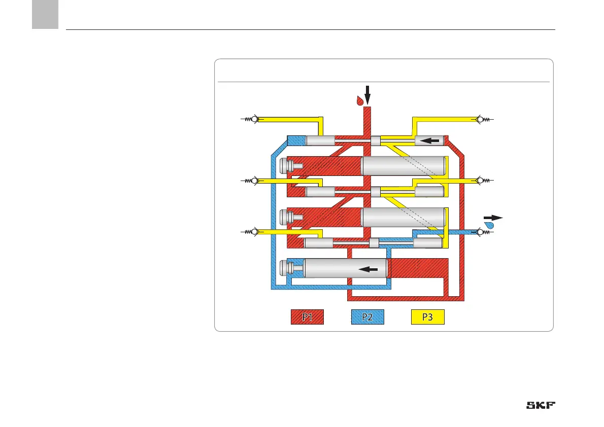
Phase 11
The control piston C2 has reached its right
end position. Thereby it opens the connec-
tion duct to the right end of control piston
A2 and metering piston A1. The pressurized
lubricant P1 is now located at the left end of
control piston A2 and metering piston A1.
Due to its larger cross-section lubricant P1
first moves metering piston A1 to the left
and then displaces the lubricant enclosed on
the left side of metering piston A1 to outlet
1.
Phase 12
As soon as metering piston A1 reaches its
left end position, the pressurized lubricant
P1 moves the control piston A2 leftward and
additionally displaces the enclosed lubricant
on the left side of control piston A2 to outlet
1.
The total output of outlet 1 corresponds to
the output of metering piston A1 and control
piston A2.
Now a full cycle of the metering device has
been completed.

 Loading...