6 Connection SMA Solar Technology AG
24 ClusterController-IA-en-10 Installation Manual
6 Connection
6.1 Overview of the Connection Area
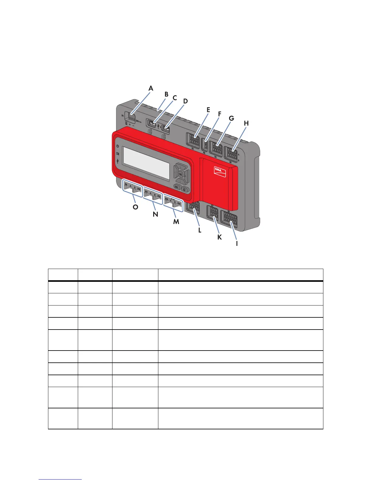
Figure9: Overview of the connection area
Item Quantity Designation Explanation
A 1 X1 Terminal for the voltage supply
B 1 ‒ Terminal for the earthing
C 1 1 USB terminal for exporting plant data
D 1 2 USB terminal for updates
E 1 X2 Digital outputs (for description of functions, see
Section 6.2)
F 1 X3 Reserved for future applications
G 1 X4 Digital inputs (for description of functions, see Section 6.2)
H 1 X5 Digital inputs (for description of functions, see Section 6.2)
I 1 X8 Analogue inputs (for description of functions, see
Section 6.2)
K 1 X7 Terminals for the temperature sensors (for description of
functions, see Section 6.2)