SMA Solar Technology AG 6 Connection
Installation Manual ClusterController-IA-en-10 49
4. On the connection cable, mark the terminal and pin row to which the connection cable is
assigned. For this purpose, use the cable ties with the caption field.
5. On the supplementary sheet for noting the connected devices, note the terminal to which the
digital signal source is assigned.
6.11.3 Analogue Signal Setpoint
6.11.3.1 Connecting the Signal Source to the Analogue Input for the
Active Power Limitation
The analogue signals for the active power limitation are sent to the terminal block Analogue current
input 2 (AI2) at terminal X8 of the Cluster Controller. A remote terminal unit can be used as an
analogue signal source, for example.
Additional required accessories (not included in scope of delivery):
☐ 1 analogue signal source
☐ Connection cable (for cable requirements, see Section 6.3)
Requirements:
☐ The analogue signal source must be able to output a current signal in the range from
0 mA to 20 mA.
☐ The connection cable must have been prepared for connection to the multipole plug
(see Section 6.5).
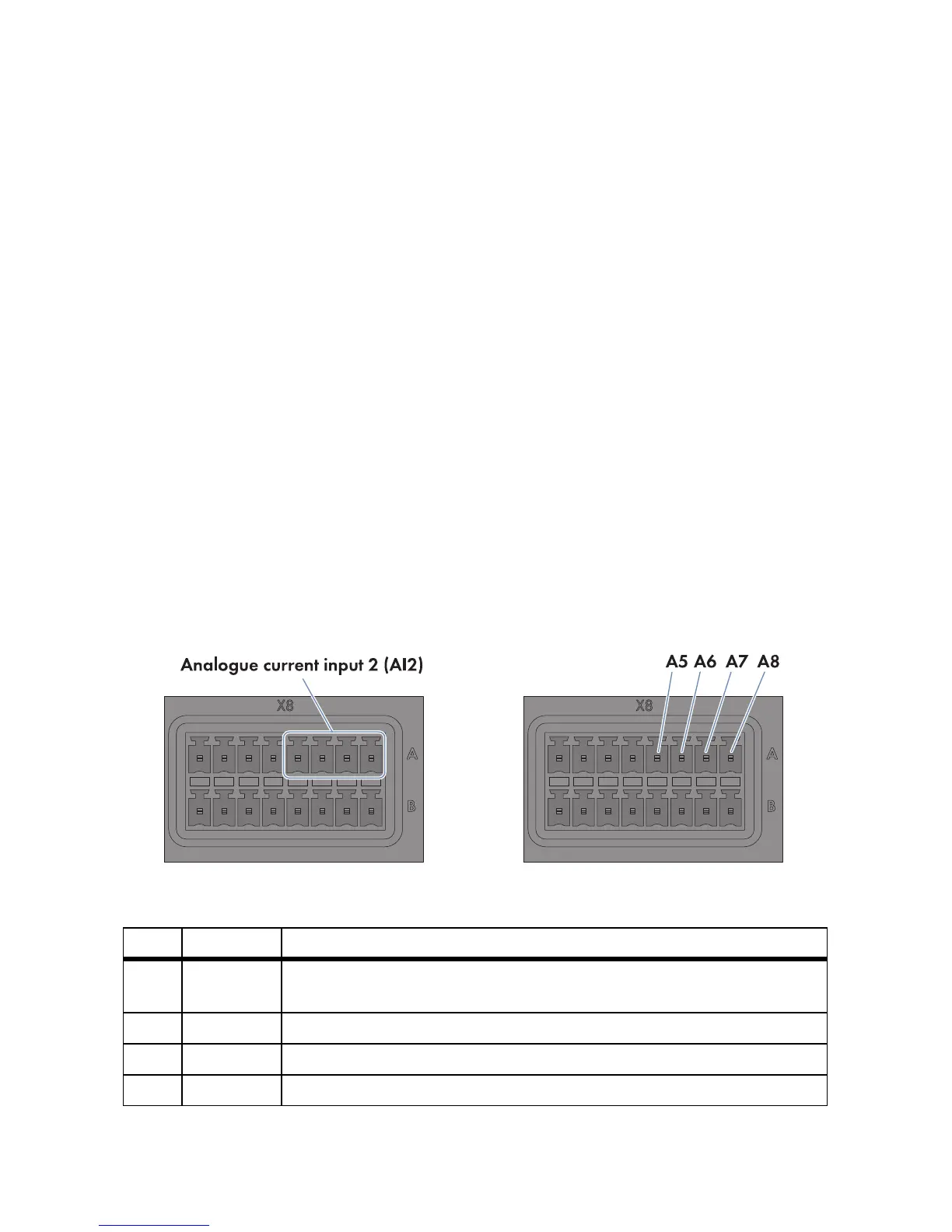
Figure19: Pin assignment at the terminal block Analogue current input 2 (AI2)
Pin Signal Explanation
A5 Not
assigned
Reserved for future applications
A6 I+ Current input
A7 I − Current feedback
A8 GND Shield ground