6 Connection SMA Solar Technology AG
58 ClusterController-IA-en-10 Installation Manual
2. Connect the connection cable to the six-pole plug as follows:
• Depending on the remote terminal and the pin assignment at the terminal blocks
Digital output 1 (DO1) and Digital output 2 (DO2), identify the conductor entries that
are required for the connection of the connection cable.
• Release the required conductor entries using a screwdriver and insert the insulated wires into
the conductor entries. Observe the pin assignment.
3. Insert the six-pole plug at terminal X2 into pin row A.
4. On the connection cable, mark the terminal and pin row to which the connection cable is
assigned. For this purpose, use the cable ties with the caption field.
5. On the supplementary sheet for noting the connected devices, note the terminal to which the
remote terminal is assigned.
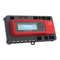
6.13 Connecting the Cluster Controller to the Voltage Supply
Procedure:
To connect the Cluster Controller to the voltage supply, perform the following actions in the specified
order. The following steps show the exact procedure.
• Connect the protective conductor to the Cluster Controller.
• Connect the top-hat rail power supply unit.
Danger to life due to electric shock if earthing is omitted
If the enclosure of the Cluster Controller is not earthed, there is a danger of electric shock.
• Earth the enclosure of the Cluster Controller.
Damage to the Cluster Controller due to condensation water
If the Cluster Controller is moved from a cold environment to a warm environment, condensation
water may form in the Cluster Controller.
• In the event of large temperature differences, only supply voltage to the Cluster Controller
once the Cluster Controller has reached room temperature.

 Loading...