SMA Solar Technology AG 6 Connection
Installation Manual ClusterController-IA-en-10 47
1. Connect the connection cable to the digital signal source (see the manufacturer manual). For
this purpose, trim the unused insulated wires up to the cable shield and note the wire colours.
2. Connect the connection cable to the six-pole plug as follows:
• Depending on the digital signal source and the pin assignment at terminal X4, identify the
conductor entries that will be required for connecting the connection cable.
• Release the required conductor entries using a screwdriver and insert the insulated wires into
the conductor entries. Observe the pin assignment.
3. Connect the six-pole plug to terminal X4. For this purpose, observe the pin coding.
4. On the connection cable, mark the terminal and pin row to which the connection cable is
assigned. For this purpose, use the cable ties with the caption field.
5. On the supplementary sheet for noting the connected devices, note the terminal to which the
digital signal source is assigned.
6.11.2.2 Connecting the Signal Source to the Digital Input for the Reactive
Power Setpoint
The digital signals for the reactive power setpoint can be sent to up to four terminal blocks at terminal
X5 of the Cluster Controller. A ripple control receiver or a remote terminal unit can be used as a
digital signal source, for example.
Additional required accessories (not included in scope of delivery):
☐ Up to four digital signal sources
☐ Connection cable (for cable requirements, see Section 6.3)
Requirement:
☐ The connection cable must have been prepared for connection to the multipole plug
(see Section 6.5).
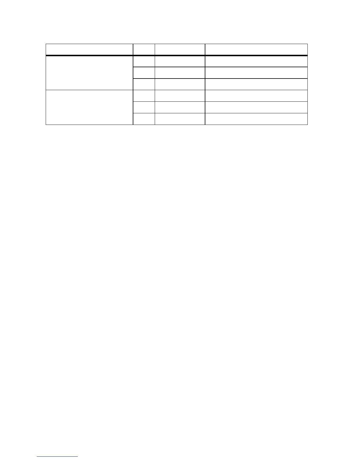
Digital input 3 (DI3)
Signal 3 of 4 for the active
power limitation
B1 24 V Voltage supply output
B2 IN Input
B3 GND Reference potential
Digital input 4 (DI4)
Signal 4 of 4 for the active
power limitation
B4 24 V Voltage supply output
B5 IN Input
B6 GND Reference potential
Terminal block Pin Pin assignment Explanation