6 Connection SMA Solar Technology AG
48 ClusterController-IA-en-10 Installation Manual
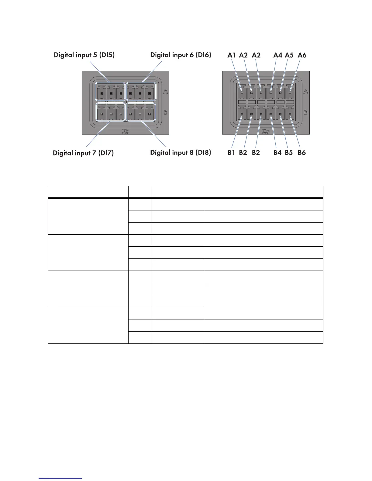
Figure18: Terminal blocks and pin assignment at terminal X5
1. Connect the connection cable to the digital signal source (see the manufacturer manual). For
this purpose, trim the unused insulated wires up to the cable shield and note the wire colours.
2. Connect the connection cable to the six-pole plug as follows:
• Depending on the digital signal source and the pin assignment at terminal X5, identify the
conductor entries that will be required for connecting the connection cable.
• Release the required conductor entries using a screwdriver and insert the insulated wires into
the conductor entries. Observe the pin assignment.
3. Connect the six-pole plug to terminal X5. For this purpose, observe the pin coding.
Terminal block Pin Pin assignment Explanation
Digital input 5 (DI5)
Signal 1 of 4 for the
reactive power setpoint
A1 24 V Voltage supply output
A2 IN Input
A3 GND Reference potential
Digital input 6 (DI6)
Signal 2 of 4 for the
reactive power setpoint
A4 24 V Voltage supply output
A5 IN Input
A6 GND Reference potential
Digital input 7 (DI7)
Signal 3 of 4 for the
reactive power setpoint
B1 24 V Voltage supply output
B2 IN Input
B3 GND Reference potential
Digital input 8 (DI8)
Signal 4 of 4 for the
reactive power setpoint
B4 24 V Voltage supply output
B5 IN Input
B6 GND Reference potential