SMA Solar Technology AG 6 Connection
Installation Manual ClusterController-IA-en-10 25
6.2 Functions of the Terminals and Terminal Blocks
The digital and analogue terminals of the Cluster Controller are divided into terminal blocks. A
terminal block is a group of pins. Each respective pin group forms one of the digital or analogue inputs
or outputs. On the enclosure, the upper row of pins is marked with A and the lower row of pins is
marked with B. The pins are counted from left to right.
The distribution of the terminals into terminal blocks and the functions of the terminal blocks are
described in the following table.
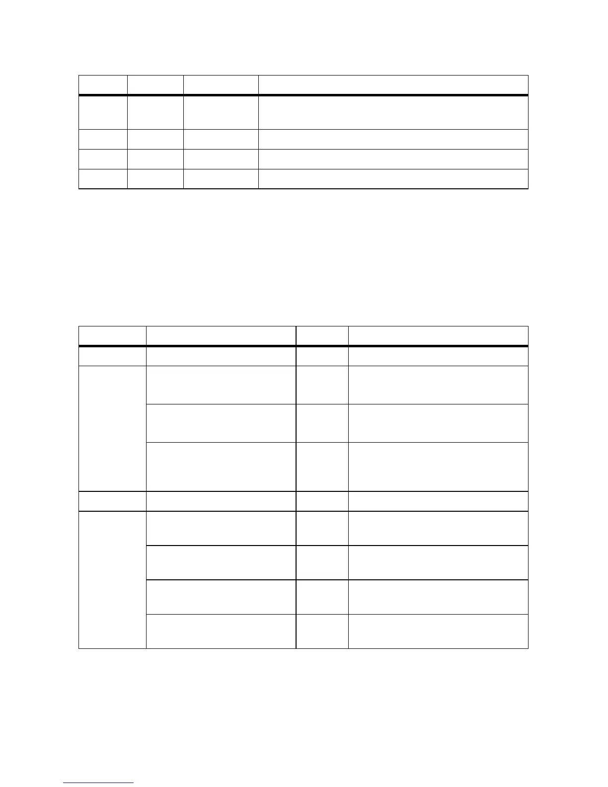
L 1 X6 Analogue outputs (for description of functions, see
Section 6.2)
M 2 X13, X14 Network terminals for local area network (LAN)
N 2 X11, X12 Reserved for future applications
O 2 X9, X10 Network terminal of the inverter (Speedwire)
Connection Terminal block Pin Function
X1 − 1 … 3 Voltage supply
X2 Digital output 1 (DO1)
Relay A
A1 … A3 Fault indication relay for the status
Fault
Digital output 2 (DO2)
Relay B
A4 … A6 Fault indication relay for the status
Warning or Fault
Digital output 3 (DO3)
Relay C
B1 … B3 Response contact for the current active
power limitation under grid
management
X3 − − Reserved for future applications
X4 Digital input 1 (DI1) A1 … A3 Signal 1 of 4 for the active power
limitation under grid management
Digital input 2 (DI2) A4 … A6 Signal 2 of 4 for the active power
limitation under grid management
Digital input 3 (DI3) B1 … B3 Signal 3 of 4 for the active power
limitation under grid management
Digital input 4 (DI4) B4 … B6 Signal 4 of 4 for the active power
limitation under grid management
Item Quantity Designation Explanation