SMA Solar Technology AG 6 Connection
Installation Manual ClusterController-IA-en-10 27
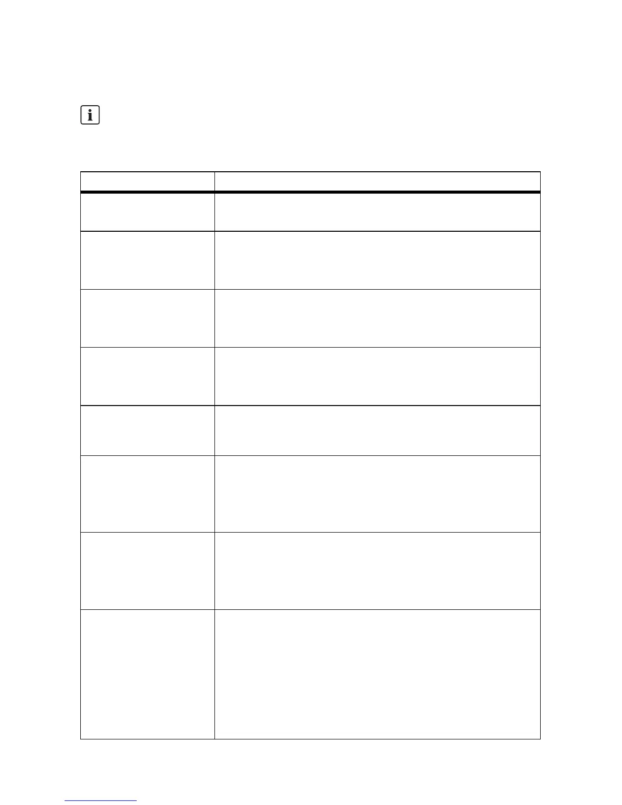
6.3 Cable Requirements
UV resistance of the connection cable
Connection cables to be laid outdoors must be UV-resistant or routed in a UV-resistant cable
channel.
Connection Cable requirements
Earthing ☐ Conductor cross-section: 2.5 mm
2
☐ Maximum cable length: 30 cm
Voltage supply ☐ Number of insulated wires: at least two
☐ Cable cross-section: 0.2 mm
2
… 2.5 mm
2
☐ Maximum cable length: 3 m
Digital inputs ☐ Number of insulated wires: at least two
☐ Cable cross-section: 0.2 mm
2
… 1.5 mm
2
☐ Maximum cable length: 30 m
Digital outputs ☐ Number of insulated wires: at least two
☐ Cable cross-section: 0.2 mm
2
… 1.5 mm
2
☐ Maximum cable length: 30 m
Analogue inputs, analogue
outputs and temperature
inputs (single core)
☐ Conductor cross-section: 1.5 mm
2
☐ Length of cable: 32 cm
Analogue inputs
(connection cable)
☐ Number of insulated wires: at least two
☐ Shielding: yes
☐ Cable cross-section: 0.2 mm
2
… 1.5 mm
2
☐ Maximum cable length: 30 m
Analogue outputs
(connection cable)
☐ Number of insulated wires: at least two
☐ Shielding: yes
☐ Cable cross-section: 0.2 mm
2
… 1.5 mm
2
☐ Maximum cable length: 3,000 m
Temperature inputs
(connection cable)
☐ Number of insulated wires for tolerance ± 2°C: at least 2
☐ Number of insulated wires for tolerance ± 0.5°C: at least 4
☐ Cable cross-section: at least 4 x 0.25 mm
2
and at least
4 x AWG 24
☐ External cable diameter: 4.5 mm … 7 mm
☐ Maximum cable length for four-conductor connection: 20 m
☐ Maximum cable length for two-conductor connection: 2.5 m