6 Connection SMA Solar Technology AG
34 ClusterController-IA-en-10 Installation Manual
6.7 Connecting the Cluster Controller to a Local Area Network
(LAN)
Additional required material (not included in scope of delivery):
☐ 1 patch cable (for cable requirements, see Section 6.3)
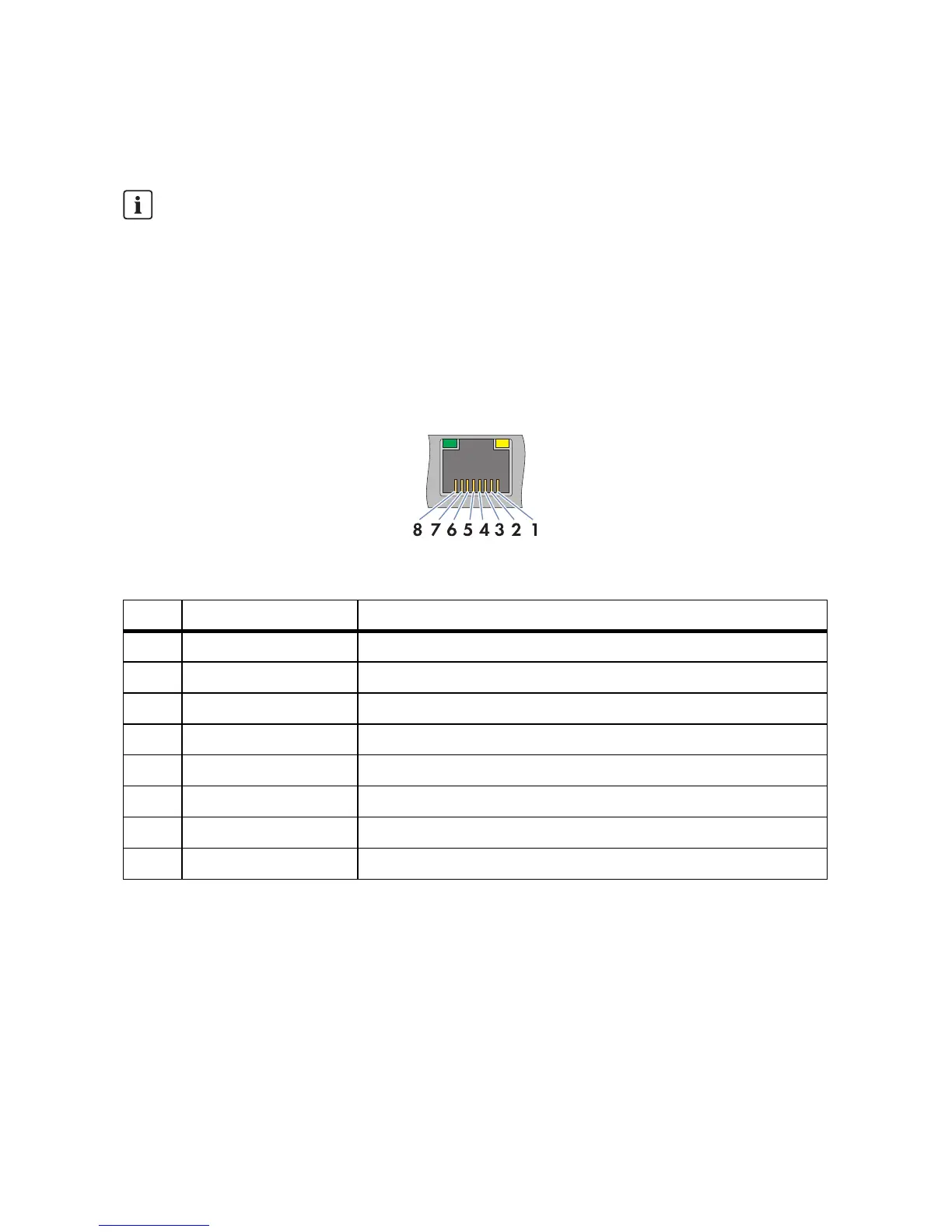
Figure11: Pin assignment at the network terminals X9, X10, X13 and X14
1. Connect the patch cable to the Cluster Controller:
• When using a pre-configured patch cable, connect the patch cable to terminal X13 or X14.
• When using a patch cable that is to be configured by the user, mount the two RJ45 plug
connectors at both ends of the patch cable (see the manufacturer manual) and connect the
patch cable to terminal X13 or X14 of the Cluster Controller.
2. Connect the other end of the patch cable to the desired node in the local area network (LAN).
3. On the supplementary sheet for noting the connected devices, note the terminal to which the
node is assigned.
Selecting a Suitable Internet Tariff
According to use, the data volume of the Cluster Controller transferred via the Internet can be
more then 1 GB per month. The data volume depends, among other things, on the number of
inverters, the frequency of device updates, the frequency of data transfer to the Sunny Portal
and the use of FTP push.
• SMA Solar Technology AG recommends using an Internet flat rate.
Pin Designation Explanation
1 TX+ Data Out +
2 TX − Data Out −
3RX+ Data In +
4GND Shield ground
5GND Shield ground
6RX− Data In−
7GND Shield ground
8GND Shield ground