SMA Solar Technology AG 6 Connection
Installation Manual ClusterController-IA-en-10 39
6.10.2 Connecting the Temperature Sensor
You can connect 1 outside temperature sensor and 1 module temperature sensor to the
Cluster Controller. The measured values of the temperature sensors are shown on the display and the
user interface of the Cluster Controller and transmitted to Sunny Portal. In Sunny Portal, the measured
values of the module temperature sensor flow into the calculation of the performance ratio.
Connecting the Outside Temperature Sensor
Additional required accessories (not included in scope of delivery):
☐ 1 outside temperature sensor
☐ 1 connection cable (for cable requirements, see Section 6.3)
Requirements:
☐ The sensor must have a PT100 measuring shunt or a PT1000 measuring shunt.
☐ The connection cable must have been prepared for connection to the multipole plug
(see Section 6.5).
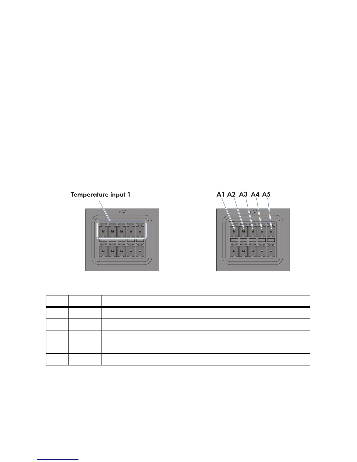
Figure13: Pin assignment at the terminal block Temperature input 1
1. Connect the connection cable to the outside temperature sensor (see the manufacturer manual).
For this purpose, trim the unused insulated wires up to the cable shield and note the wire colours.
Pin Signal Explanation
A1 GND Shield ground
A2 I+ Current input
A3 V+ Voltage input
A4 V − Voltage feedback
A5 I − Current feedback