6 Connection SMA Solar Technology AG
40 ClusterController-IA-en-10 Installation Manual
2. Connect the connection cable to the five-pole plug as follows:
• Release conductor entry 1 using a screwdriver and insert the insulated wire of the single core
into the conductor entry.
• For two-conductor connection, release conductor entries 3 and 4 using a screwdriver and
insert the insulated wires of the connection cable into the conductor entries. Observe the pin
assignment.
• For four-conductor connection, release conductor entries 2, 3, 4 and 5 using a screwdriver
and insert the insulated wires of the connection cable into the conductor entries. Observe the
pin assignment.
3. Insert the five-pole plug at terminal X7 into pin row A.
4. On the connection cable, mark the terminal and pin row to which the connection cable is
assigned. For this purpose, use the cable ties with the caption field.
5. On the supplementary sheet for noting the connected devices, note the terminal to which the
sensor is assigned.
Connecting the Module Temperature Sensor
Additional required accessories (not included in scope of delivery):
☐ 1 module temperature sensor
☐ 1 connection cable (for cable requirements, see Section 6.3)
Requirements:
☐ The sensor must have a PT100 measuring shunt or a PT1000 measuring shunt.
☐ The connection cable must have been prepared for connection to the multipole plug
(see Section 6.5).
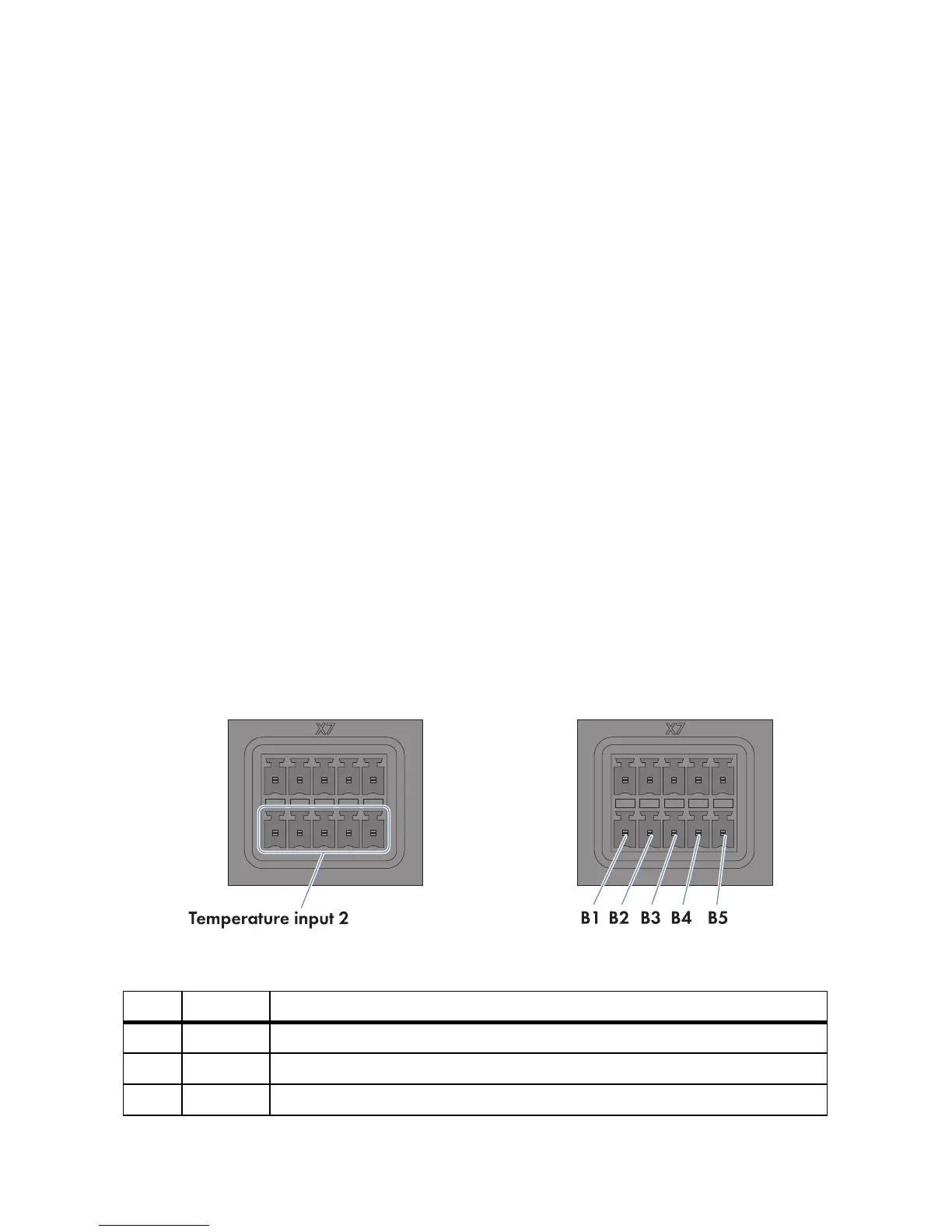
Figure14: Pin assignment at the terminal block Temperature input 2
Pin Signal Explanation
B1 GND Shield ground
B2 I+ Current input
B3 V+ Voltage input