6 Connection SMA Solar Technology AG
46 ClusterController-IA-en-10 Installation Manual
6.11.2 Digital Signal Setpoint
6.11.2.1 Connecting the Signal Source to the Digital Input for the Active
Power Limitation
The digital signals for the active power limitation can be sent to up to four terminal blocks at terminal
X4 of the Cluster Controller. A ripple control receiver or a remote terminal unit can be used as a
digital signal source, for example.
Additional required accessories (not included in scope of delivery):
☐ Up to four digital signal sources
☐ Connection cable (for cable requirements, see Section 6.3)
Requirement:
☐ The connection cable must have been prepared for connection to the multipole plug
(see Section 6.5).
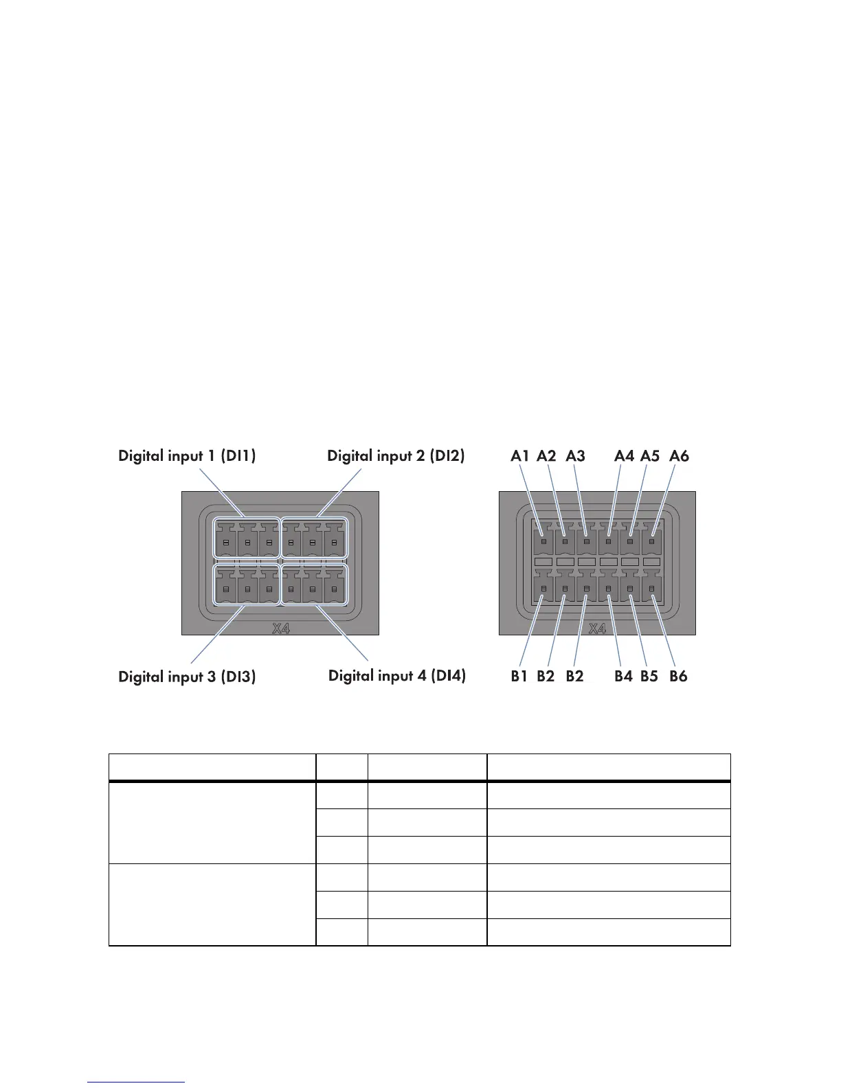
Figure17: Terminal blocks and pin assignment at terminal X4
Terminal block Pin Pin assignment Explanation
Digital input 1 (DI1)
Signal 1 of 4 for the active
power limitation
A1 24 V Voltage supply output
A2 IN Input
A3 GND Reference potential
Digital input 2 (DI2)
Signal 2 of 4 for the active
power limitation
A4 24 V Voltage supply output
A5 IN Input
A6 GND Reference potential