SMA Solar Technology AG 6 Connection
Installation Manual ClusterController-IA-en-10 57
6.12 Using Fault Indication Relays
You can connect up to three remote terminals (e.g. optical or acoustic signal generators) to the three
potential-free relay contacts of the Cluster Controller. The relay contacts are implemented as two fault
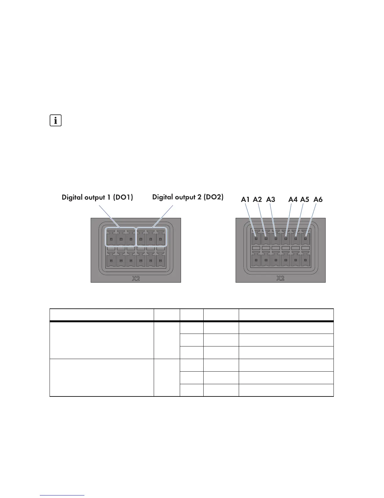
indication relays and one response contact. Via the fault indication relay Digital output 1 (DO1),
you can signal the plant status Fault. Via the fault indication relay Digital output 2 (DO2), you can
signal the plant status Fault or Warning.
Requirement:
☐ The connection cable must have been prepared for connection to the multipole plug (see
Section 6.5).
Figure26: Pin assignment at the terminal blocks Digital output 1 (DO1) and Digital output 2 (DO2)
1. Connect the connection cable to the remote terminal (see the manufacturer manual). For this
purpose, trim the unused insulated wires up to the cable shield and note the wire colours.
Observe the maximum load capacity of the relay contacts
The relay contacts may be loaded with a maximum switching capacity of 30 watts and a
maximum voltage of 48 V DC (see Section9 "Technical Data", page77).
Terminal block Relay Pin Signal Explanation
Digital output 1 (DO1)
Fault indication relay for the plant
status Fault
AA1NC Back contact
A2 CO Change-over contact
A3 NO Front contact
Digital output 2 (DO2)
Fault indication relay for the plant
status Fault or Warning
BA4NC Back contact
A5 CO Change-over contact
A6 NO Front contact