6 Connection SMA Solar Technology AG
42 ClusterController-IA-en-10 Installation Manual
Requirements:
☐ The sensor must be able to output a current signal in the range from 0 mA to 20 mA.
☐ The connection cable must have been prepared for connection to the multipole plug
(see Section 6.5)
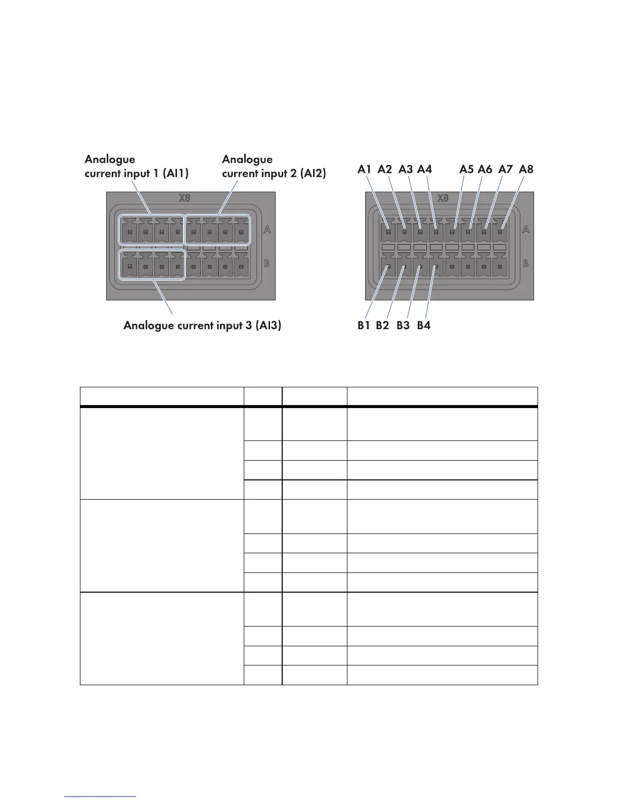
Figure15: Pin assignment at the terminal blocks Analogue current input 1 (AI1), Analogue current input 2
(AI2) and Analogue current input 3 (AI3)
1. Connect the connection cable to the sensor (see the manufacturer manual). For this purpose,
trim the insulated wires that are not required up to the cable shield and note the wire colours.
Terminal block Pin Signal Explanation
Analogue current input 1 (AI1) A1 Not
assigned
Reserved for future applications
A2 I+ Current input
A3 I − Current feedback
A4 GND Shield ground
Analogue current input 2 (AI2) A5 Not
assigned
Reserved for future applications
A6 I+ Current input
A7 I − Current feedback
A8 GND Shield ground
Analogue current input 3 (AI3) B1 Not
assigned
Reserved for future applications
B2 I+ Current input
B3 I − Current feedback
B4 GND Shield ground