6 Connection SMA Solar Technology AG
44 ClusterController-IA-en-10 Installation Manual
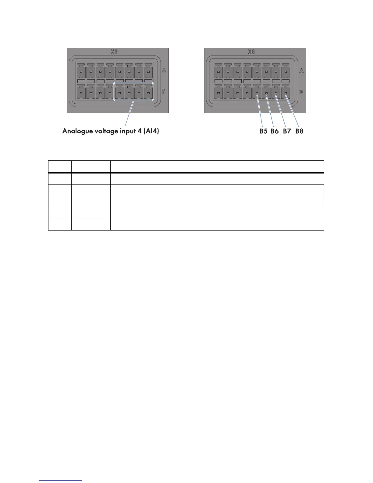
Figure16: Pin assignment at the terminal block Analogue voltage input 4 (AI4)
1. Connect the connection cable to the sensor (see the manufacturer manual). For this purpose,
trim the insulated wires that are not required up to the cable shield and note the wire colours.
2. Connect the connection cable to the eight-pole plug as follows:
• Release conductor entry 8 using a screwdriver and insert the insulated wire of the single core
into the conductor entry.
• Release conductor entries 5 and 7 using a screwdriver and insert the insulated wires of the
connection cable into the conductor entries. Observe the pin assignment.
3. Insert the eight-pole plug at terminal X8 into pin row B.
4. On the connection cable, mark the terminal and pin row to which the connection cable is
assigned. For this purpose, use the cable ties with the caption field.
5. On the supplementary sheet for noting the connected devices, note the terminal to which the
sensor is assigned.
Pin Signal Explanation
B5 V+ Voltage input
B6 Not
assigned
Reserved for future applications
B7 V − Voltage feedback
B8 GND Shield ground