HRX-OM-W002-A
Chapter 5 Display and Setting of Various Functions
HRR Series 5.5 Advanced setting mode
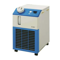
Table 5.5-1 List of alarms for which isolated pump operation is available
* 1 Select from OFF/ WRN/ FLT 2 Select from WRN/ FLT.
* 3 Can be set only for air-cooled type.
* 4 Option DM (Electric conductivity control type, de-ionized water piping type) only. Alarm is
automatically released when the electric conductivity returns within the range.
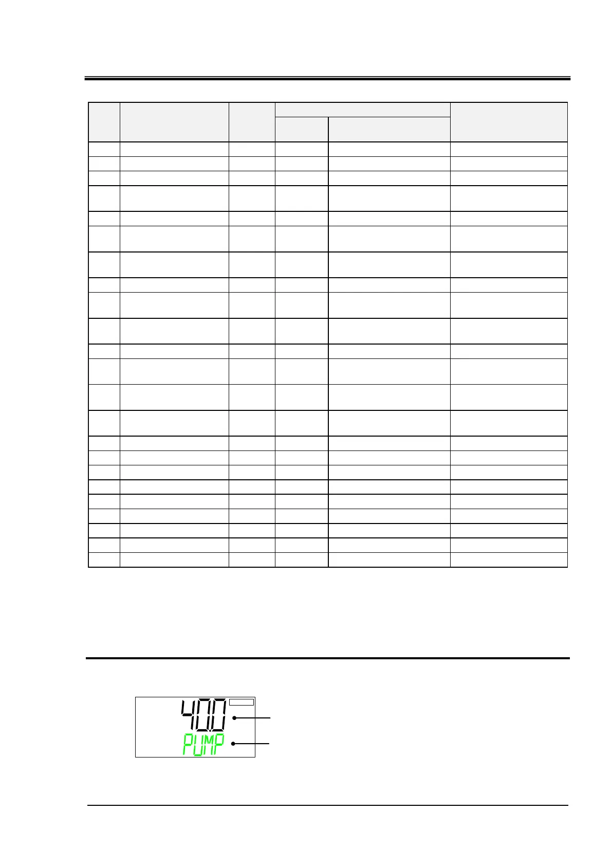
Temperature for pump to continue operation when alarm is generated.
28. Press the [▼] key. Displays screen for setting the upper limit of temperature for the
pump to continue operation when an alarm is generated.
●Setting range: 10.0 to 45.0℃ (initial value: 40.0℃)
Refer to P.5-42 “Isolated operation of the pump” for settings.
PUMP ⇒ TEMP(Alternately displayed)
Upper limit of the circulating fluid temperature for isolated
operation of the pump
AL01 Low level in tank FLT AL01 LOW⇒LEVEL⇒FLT -
AL02 Low level in tank WRN AL02 LOW⇒LEVE⇒WRN -
AL04 Water leakage
WRN
1
AL04 WATER ⇒ LEAK ○
Circulating fluid
discharge pressure rise
AL10 Flow rate decreased
WRN
1
AL10 LOW⇒FLOW⇒WRN ○
Ambient temperature is
out of the range *3
Electric conductivity
increase *4
AL13 NOT TEMP READY
OFF
1
AL13 TEMP⇒READY⇒ERROR ○
Circulating fluid
temperature increase
Circulating fluid
temperature decrease
AL17 Low flow rate FLT AL17 LOW⇒FLOW⇒FLT -
High circulating fluid
discharge temp.
High circulating fluid
return temp.
High circulating fluid
discharge pressure
FLT AL21 HIGH⇒PRESS⇒FLT -
AL24 Memory error FLT AL24 MEM ⇒ ERROR ○
AL25 Contact input 1
FLT
1
AL25 INP1 ⇒ ERROR ○
AL26 signal detection
FLT
1
AL26 INP2 ⇒ ERROR ○
AL27 Contact input 2 FLT AL27 FORCE ⇒ STOP -
AL28 signal detection
OFF
1
AL28 MANT ⇒ ALARM ○
AL29 Forced stop
WRN
1
AL29 COMM ⇒ ERROR ○
AL30 Notice for maintenance FLT AL30 REF⇒ERROR⇒0000 ○
AL31 Communication error FLT AL31 SENS⇒ERROR⇒0000 -
AL32 Compressor circuit error FLT AL32 CTRL⇒ERROR⇒0000 -
Alarms for which isolated
pump operation is
available

 Loading...