HRX-OM-Q026
Chapter 5 Display and Setting of Various Functions
5.2 Function HRSH Series
5-6
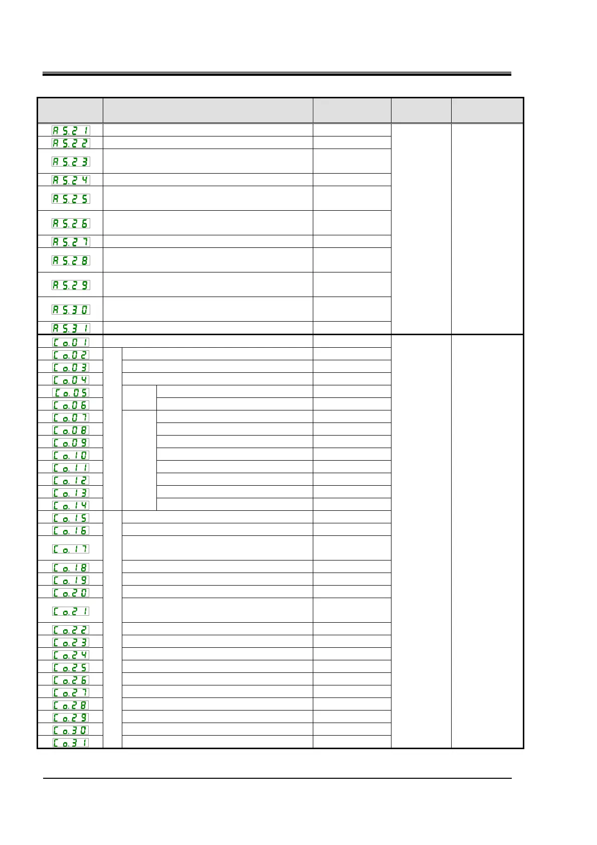
Table 5.2-3 List of parameters (3/3)
Temperature alarm monitoring method
Operation setting for the monitoring start timer
Threshold time setting for the range over
detection timer
Alarm settings for the compressor
Operation setting when "Circulating fluid discharge
pressure sensor failure " alarm is generated
Operation setting during maintenance of the
pump
Operation setting during maintenance of the fan
Operation setting during maintenance of the
compressor
Operation setting during maintenance of the
dust-proof filter
Operation setting at a time of operation
restoration after power failure
Changing of the dust-proof filter maintenance time
Communicati
on
setting menu
Communication specification
RS-485 terminating resistor
Simple communication
protocols
Contact input/output communication
Contact input signal 1 type
Contact input signal 1 delay timer (time
delay) for reading
Contact input signal 1 OFF detection timer
Contact input signal 2 type
Contact input signal 2 delay timer (time
delay) of reading
Contact input signal 2 OFF detection timer
Contact output signal 1 function
Contact output signal 1 operation
Contact output signal 1 selected alarm
Contact output signal 2 function
Contact output signal 2 operation
Contact output signal 2 selected alarm
Contact output signal 3 function
Contact output signal 3 operation
Contact output signal 3 selected alarm
*7: For more details of the default settings, refer to “5.21 Alarm Customizing Function”.
*8: For more details of the default settings, refer to “5.22 Communication Function”.
 Loading...


