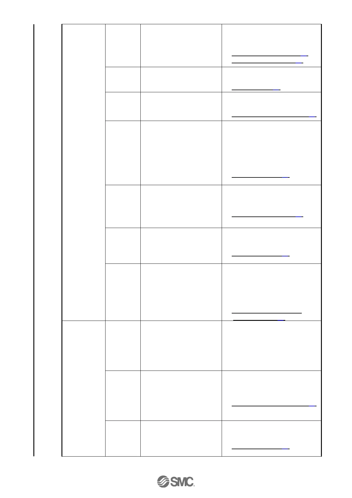
Operation stops
intermittently
Is the wiring connected
correctly?
Refer to the controller operation
manual to confirm wiring, and
check for broken wires and
short-circuits.
Correct the wiring so that the
input/output of each signal is performed
appropriately.
→ 5. External Connections (P.23)
→ 9.1 Memory allocation (P.32)
Connect to Ground correctly.
Avoid bundling the cables.
Refer to the controller operation manual
and take appropriate measures.
→ 3.4 Mounting (P.16)
Check that the parameter
values are correct.
Also, check the cables are not
bundled.
Take appropriate measures according
to this manual.
→ 10. Settings and Data Entry (P.41)
Check for a temporary voltage
drop in the power supply?
(If there is a temporary voltage
drop in the power supply, the
“EMG” signal from the PWR
connector will turn OFF so the
actuator will stop. However, this
stop will be released when the
voltage recovers.)
There is a possibility of a momentary
voltage drop because the capacity of
the power supply is insufficient, or if the
power supply is "inrush-current control"
type.
If necessary, replace the power supply.
→ 3. Specifications (P.12)
Failure of
pushing
operation.
Check that “INP” turns ON
during a pushing operation.
(If completion of the pushing
operation is detected by “INP”,
the PLC cannot confirm
completion)
Check “INP” signal before the energy
saving mode is turned ON.
→ 9.1 Memory allocation (P.32)
Check if the controller’s
specifications are appropriate,
the power supply is suitable and
the controller is compatible with
the actuator.
Take appropriate measures according
to this manual.
→ 3. Specifications (P.12)
Check the timing of the signal
from the PLC to the controller.
Set the interval time between signals to
more than twice the communication
cycle time, when the signals are to be
continuously input, because PLC
processing delays and controller
scanning delays can occur.
→ 11.4 Controller input signal
response time (P.49)
The actuator
does not move
to the correct
position.
Incorrect
origin
position
If it is a pushing operation, repeat
return to origin operations several
times to check if the actuator
returns to the origin correctly.
Perform the Return to Origin
position operation several times
to check the Origin position.
Take measures to make the actuator
operate normally (remove foreign
matter that interferes with the actuator
movement, etc.)
Check that the parameter
values are appropriate and the
program is correct.
Review the maximum speed, the
maximum acceleration and the
maximum deceleration of the
actuator.
Modify the parameters and test the
operation.
→ 10. Settings and Data Entry (P.41)
Check if the controller’s
specifications are appropriate,
the power supply is suitable and
the controller is compatible with
the actuator.
Take appropriate measures according
to this manual.
→ 3. Specifications (P.12)

 Loading...


