-33-
No.SFOD-OMT0006-F
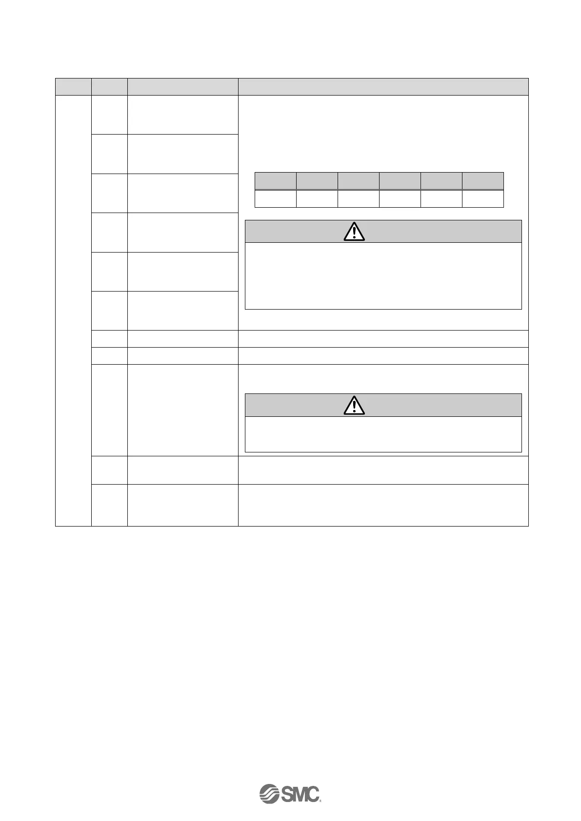
(2) Input area mapping of upper level device
●Word0: Signals allocated to the input port
When the operation is started and “DRIVE” is turned OFF,
the step No. executed by “DRIVE” will be refreshed/updated
by the combination of “OUT0” to “OUT5” (binary digit).
(E.g.) Step data No.3 is output
(1) When “RESET” is turned ON, these signals turn OFF.
(2) During the alarm, these signals output the alarm group.
(3) During the pushing operation, if the actuator runs over
the defined pushing width, these signals turn OFF.
This signal is ON during the movement of the actuator (during
the positioning operation, etc.).
During the pushing operation without movement (no
movement but the actuator generating the pushing force),
“BUSY” is OFF.
When the servo motor is OFF, “SVRE” is OFF. When the
servo motor is ON, “SVRE” is ON.
When the actuator is in the SETON status (the position
information is established), this signal turns ON.
When the position status is not established, this signal is OFF.

 Loading...


