-10-
No.SFOD-OMT0006-F
(6) Supply of power
Supply power 24VDC.
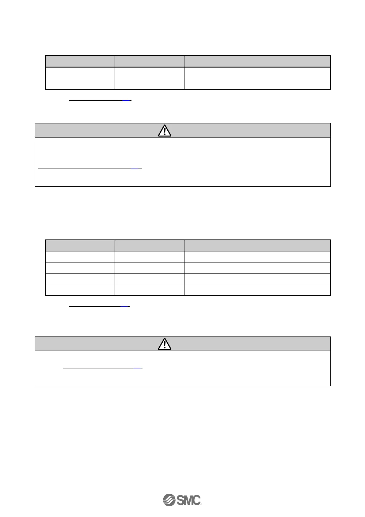
If the condition is normal, LED on the front of the controller turns ON as the table below when power
is supplied.
Refer to
7. LED display (P.30)
for the explanation of LED lamps.
If the red [ALM] LED on the front of the controller (JXC) is ON, the alarm has been triggered.
When an alarm is generated
Refer to a corresponding memory of EtherNet/IP or connect a PC or teaching box to the SI serial I/O
connector and check the details of the alarm. Then, remove the cause of the error referring to the
15. Alarm for Motor Control (P.62).
Please refer to the manuals of the controller setting software or the teaching box for details of the
alarms.
(7) Setting parameters
It is necessary to set the controller parameters.
The status of the LEDs on the front of the controller matches the table below when the setting of PLC
and parameters complete properly and EtherNet/IP communication is established.
EtherNet/IP communications established.
Refer to
7 LED display (P.30)
for the explanation of LED lamps.
Communication between PLC and controller is not established when LED[NS] on the front of the
controller(JXC) is OFF, green LED flashes, or red LED flashes or turns ON.
Communication between PLC and controller is not established.
Refer to
19. Troubleshooting (P.78)
Check if the communication speed of the PLC and controller and the information of the host computer
are correctly set.

 Loading...


