-44-
No.SFOD-OMT0006-F
10.2 Basic parameters
The "Basic parameter" is the data to define the operating conditions of the controller, conditions of the
actuator, etc.
Details of basic parameters
Activation: "■" = Effective as soon as it is recorded into the controller
"○" = Become effective after restarting the controller
"-" = The parameter cannot be changed (fixed value)
Controller
setting
software
Identification number (axis) parameters of serial
communications are set.
This is the fixed value for this controller.
( Do not change the setting)
The value for this should be 64 (Standard).
Acceleration
/deceleration
pattern
Acceleration
/deceleration
pattern
This is the fixed value for this controller.
( Do not change the setting)
This defines the trapezoidal acceleration/deceleration parameter.
This is the fixed value for this controller.
( Do not change the setting)
This defines the positive (+) side limit of the position. (Unit: mm)
Any value greater than the [stroke(+)] value cannot be entered in
the "Position" field data of step parameter setup.
This defines the positive (+) side limit of the position. (Unit: mm)
Any value less than the [stroke(-)] value cannot be entered in the
"Position" field data of step parameter setup.
This defines the maximum limit of the speed. (Unit: mm/s)
Any value greater than the [Max speed] value cannot be entered
in the "Speed" field data of step parameter setup.
Maximum
acceleration
speed
Maximum
acceleration
/Deceleration
speed
This defines the maximum limit of the ACC/DEC. (Unit: mm/s
2
)
Any value greater than the [Max ACC/DEC] value cannot be
entered in the "Accel" field data of step parameter setup.
This defines the range to activate the INP when the actuator is
within it after the return to origin operation. (Unit: mm)
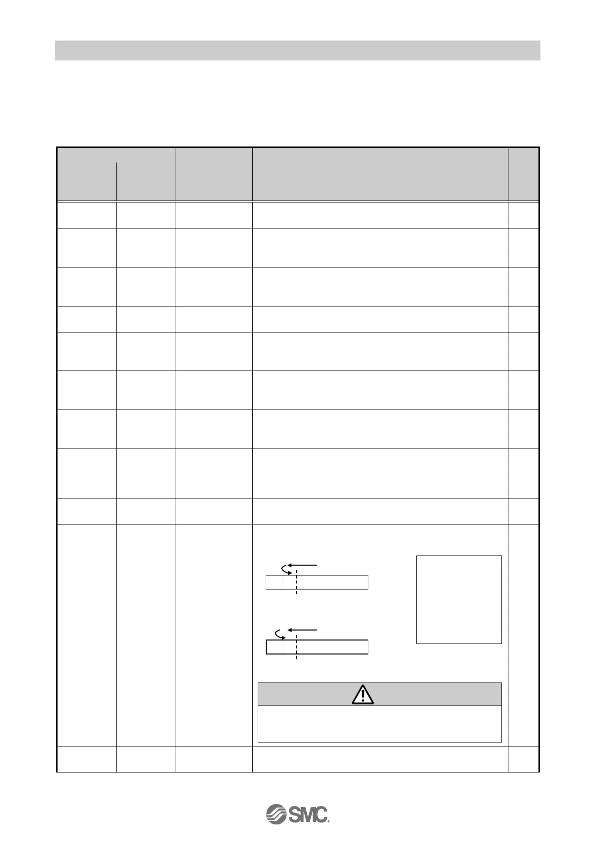
This defines the position of the actuator after the return to
origin operation. (Unit: mm)
■The ORIG offset is 0 (mm).
■The ORIG offset is 100 (mm).
If the value for the "ORIG offset" is changed, the "Stroke
(+)" and "Stroke (-)" of the basic parameters should be
checked.
The maximum force for the pushing operation. (Unit %)
In the examples on the
left, the actuator
positions are not different
but the reference point
that the controller
recognizes will be
changed after the return
to origin operation.
The position is identified by the controller after
the return to the origin operation (0mm).
The position is identified by the controller after
the return to the origin operation (100mm).
 Loading...


