-37-
No.SFOD-OMT0006-F
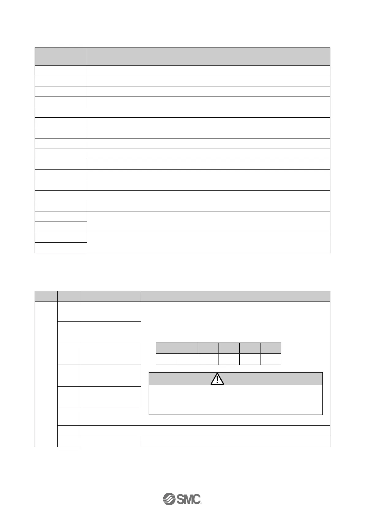
(3) Output area mapping
●From upper devices to controller
Output port to which signals are allocated
Controlling of the controller/numerical data flag
Target Position (Lower digits)
Target Position (Upper digits)
Pushing force (Thrust setting value)
(4) From upper devices to controller (details)
●Word0: Output port to which signal is allocated
The step data No. instruction the drive will be specified by the
combination of “IN0” to “IN5” (binary digit).
E.g.) Step data No.3 has been assigned
Be sure to decide the step data No. via the “IN*” signal before
turning “DRIVE” ON.
Otherwise, the actuator might operate with unexpected step
data.

 Loading...


