EasyManuals Logo
Home>SMC Networks>Controller>JXC91

SMC Networks JXC91 User Manual

SMC Networks JXC91
86 pages
To Next Page IconTo Next Page
To Previous Page IconTo Previous Page
Page #37 background imageLoading...
Page #37 background image
-36-
No.SFOD-OMT0006-F
Word6, 7: Target position
Word
Bit
Signal name
Description
6
0-15
Target Position
(Lower digits)
Target position of the actuator is shown in multiples of
0.01mm when numerical data can be read. (5)
7
0-15
Target Position
(Upper digits)
Word8, 9: Alarm
Word
Bit
Signal name
Description
8
0-7
Alarm 1
Alarm code shown as a 3 digits decimal number when read
numerical data is valid and alarm is generated. (5)
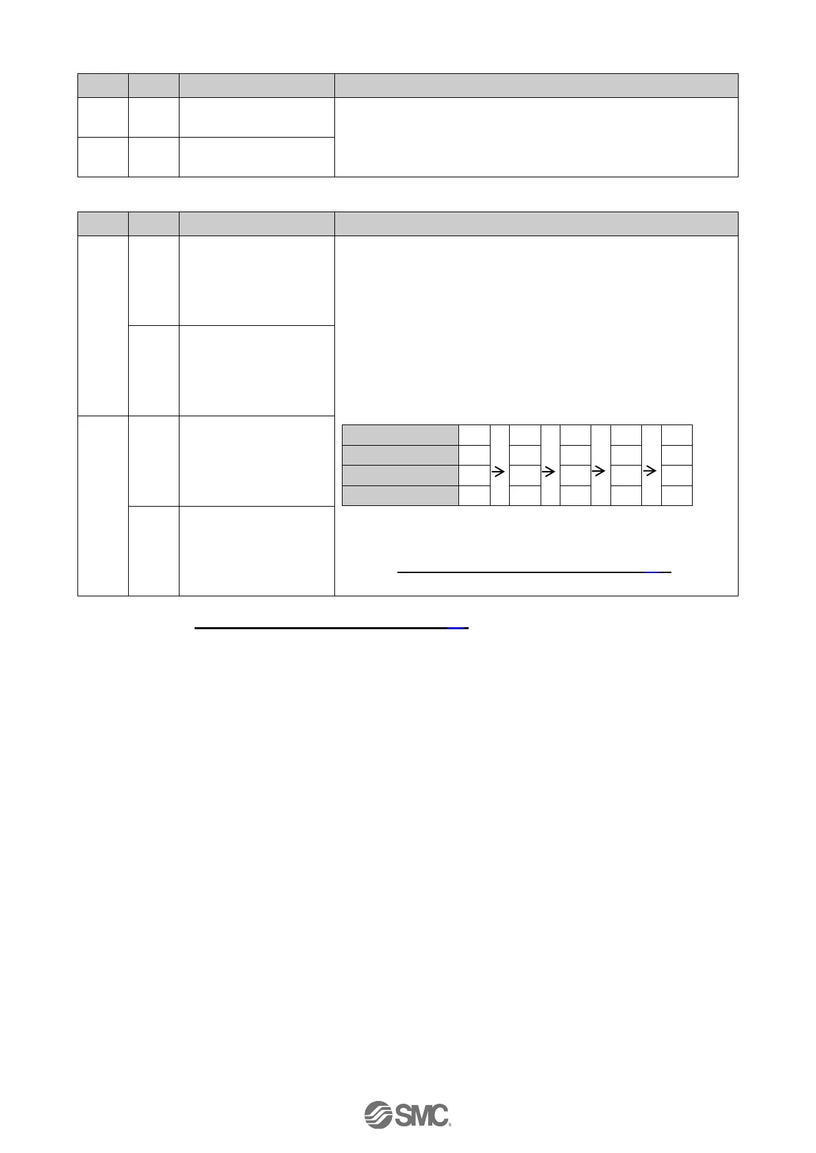
Latest alarm code generated will be output to alarm 1.
Alarm is updated by another alarm. The code of the alarm
generated in the past will be shifted as alarm 1 2 3 4.
When the number of alarm generated exceeds the maximum
alarm output of each tool (PC Setting Software or Teaching
box), the oldest alarm code is deleted from the record.
E.g.) Alarm was generated in order of (1) (5)
Alarm 1 (Latest)
(1)
(2)
(3)
(4)
(5)
Alarm 2
0
(1)
(2)
(3)
(4)
Alarm 3
0
0
(1)
(2)
(3)
Alarm 4
0
0
0
(1)
(2)
(1) to (5) in the table indicates the alarm codes which are
generated.
Refer to "15.2. Alarm and troubleshooting (P.63)" for
detailed alarm information.
8-15
Alarm 2
9
0-7
Alarm 3
8-15
Alarm 4
5 Please refer to 20. Handling of sent/received data (P.83) for handling of the data.

Table of Contents

Questions and Answers:

Question and Answer IconNeed help?

Do you have a question about the SMC Networks JXC91 and is the answer not in the manual?

SMC Networks JXC91 Specifications

General IconGeneral
BrandSMC Networks
ModelJXC91
CategoryController
LanguageEnglish

Related product manuals