Servodrives / inverters series COSMOS 301X Installation, use and maintenance manual - EN
5.7 24V auxiliary and I/O power
The family of servo-drives/inverters can be equipped with one or more connectors for connecting 24V
auxiliary power (where required) and I/Os. The following paragraphs describe the pin configuration of the
connectors.
All servo-drive versions feature removable spring-loaded connectors; the acceptable cross-sections of the
cables to be used for wiring are as follows:
Minimum cross-section of solid conductor * ** 0.20 mm
2
Maximum cross-section of solid conductor * ** 1.5 mm
2
Minimum cross-section of flexible conductor * ** 0.20 mm
2
Maximum cross-section of flexible conductor * ** 1.5 mm
2
Minimum cross-section of flexible conductor with terminal * ** 0.25 mm
2
Maximum cross-section of flexible conductor with terminal * ** 0.75 mm
2
*= Use 60/75 °C wires only (UL)
**= Use Copper Conductors only (UL)
Use a flat-head screwdriver to wire the connector; insert the edge of the head into the orange cavity and
press to open the contact. At the same time, insert the cable. It is recommended to use a screwdriver with a
2.5 mm flat head.
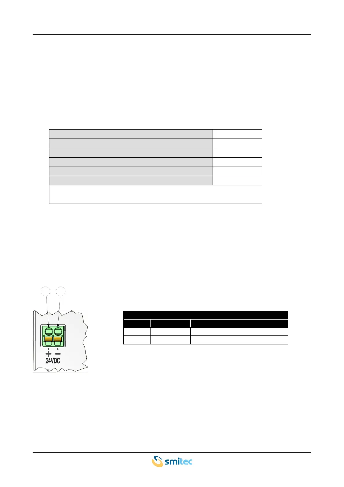
5.7.1 Connections (KZ010374)
This version is equipped with a removable connector for wiring 24V auxiliary power. Here is the pin
configuration of the connector:
24V power supply
pin label signal
1 24VDC + 24VDC power – positive side
2 24VDC - 24VDC power – negative side
Ver. 1.09 SMITECdd 41/74