Servodrives / inverters series COSMOS 301X Installation, use and maintenance manual - EN
5.7.11 Incremental encoder
An encoder is used as a feedback device for reading and controlling the motor position and speed. These
servo-drives are equipped with a peripheral device that can acquire data from incremental digital encoders,
which are powered by 5 VDC and have differential output signals. Differential outputs offer grater noise
rejection than common single-ended outputs. When brushless motors are used, it is necessary to know also
the rotor initial position; therefore, the encoder must also be equipped with three Hall-effect sensors. The
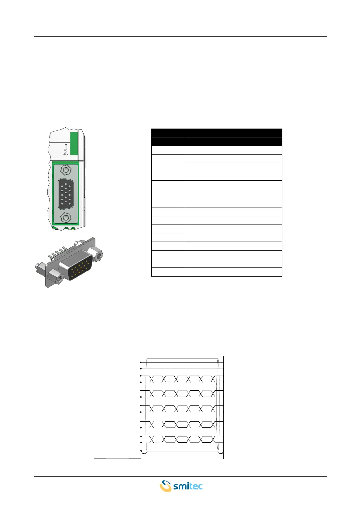
connector used on the encoder is removable; the following picture shows the pin configuration:
Incremental encoder
pin signal
1 Temperature sensor – pin 1
2 Temperature sensor – pin 2
3 +5VDC
4 GND
5 earth
6 A+ channel
7 B+ channel
8 Hall U+
9 Hall V+
10 Hall W+
11 A- channel
12 B- channel
13 Hall U-
14 Hall V-
15 Hall W-
The interface for the Hall sensors is only provided on versions that can also pilot brushless motors. Carefully
check the signal polarity before connecting the encoder; otherwise, the motor might rotate uncontrollably.
Risk of electrical and/or mechanical damage to the system.
The following picture shows an example of connection; in case of asynchronous motor, the Hall sensors are
not included.
Ver. 1.09 SMITECdd 50/74