Servodrives / inverters series COSMOS 301X Installation, use and maintenance manual - EN
5.7.12 Resolver
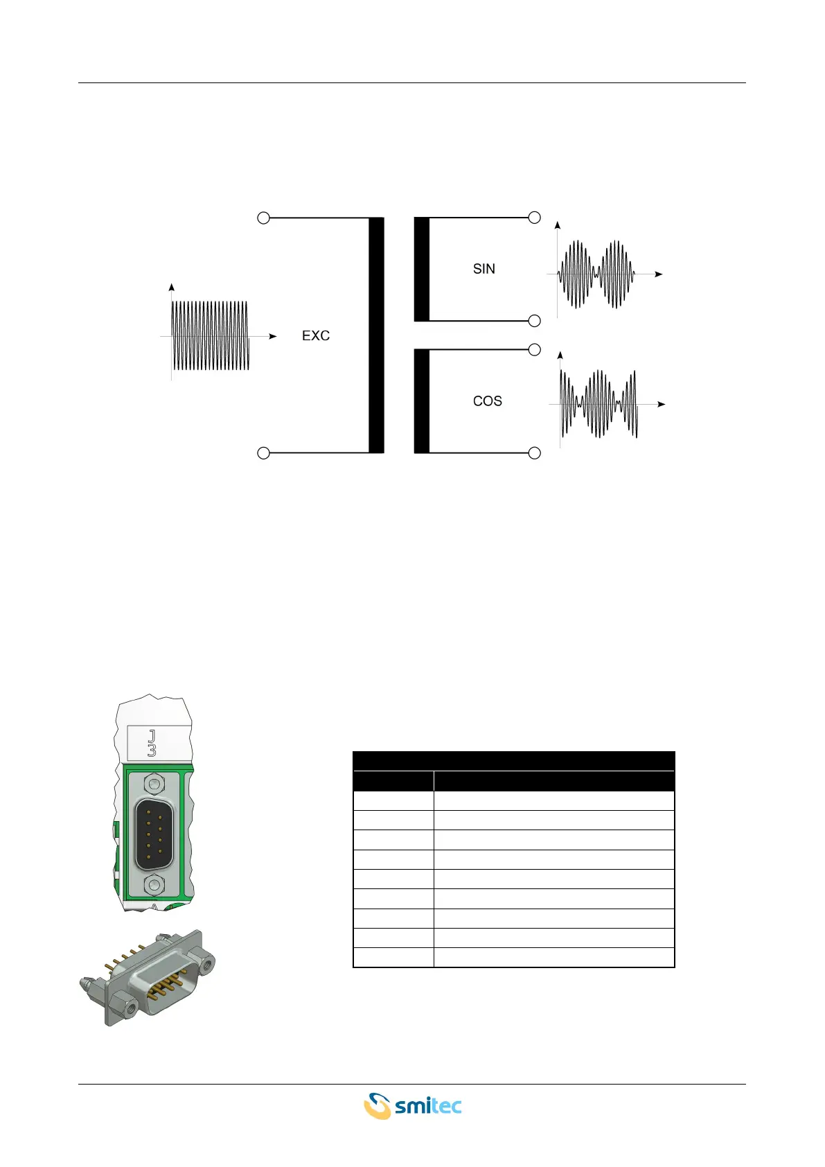
Some versions of the servo-drive are equipped with a peripheral unit for the acquisition of resolvers, used as
a feedback for reading and controlling the motor position and speed. The schematic diagram of this
transducer is shown in the following picture:
The resolver operates as follows: the servo-drive generates a sinusoidal excitation signal with a constant
frequency (10 kHz) and amplitude. The resolver features two output coils that generate two sinusoidal
signals at the same frequency as the excitation signal, but with an amplitude that depends on the mechanical
angle between rotor and stator. By measuring the two instantaneous amplitudes, it is possible to determine
the position on the rotor, in a way that is completely similar to the method used in a digital encoder.
The connector for the resolver is removable; the pin configuration and a diagram of the connector are shown
in the following picture:
Resolver
pin signal
1 GND
2 SIN+
3 SIN-
4 EXC-
5 EXC+
6 COS-
7 temperature sensor – pin 1
8 temperature sensor – pin 2
9 COS+
Ver. 1.09 SMITECdd 52/74