Servodrives / inverters series COSMOS 301X Installation, use and maintenance manual - EN
The connections for the motor temperature sensor are also provided on pins 1 and 2 of the connector (see
specific paragraph).
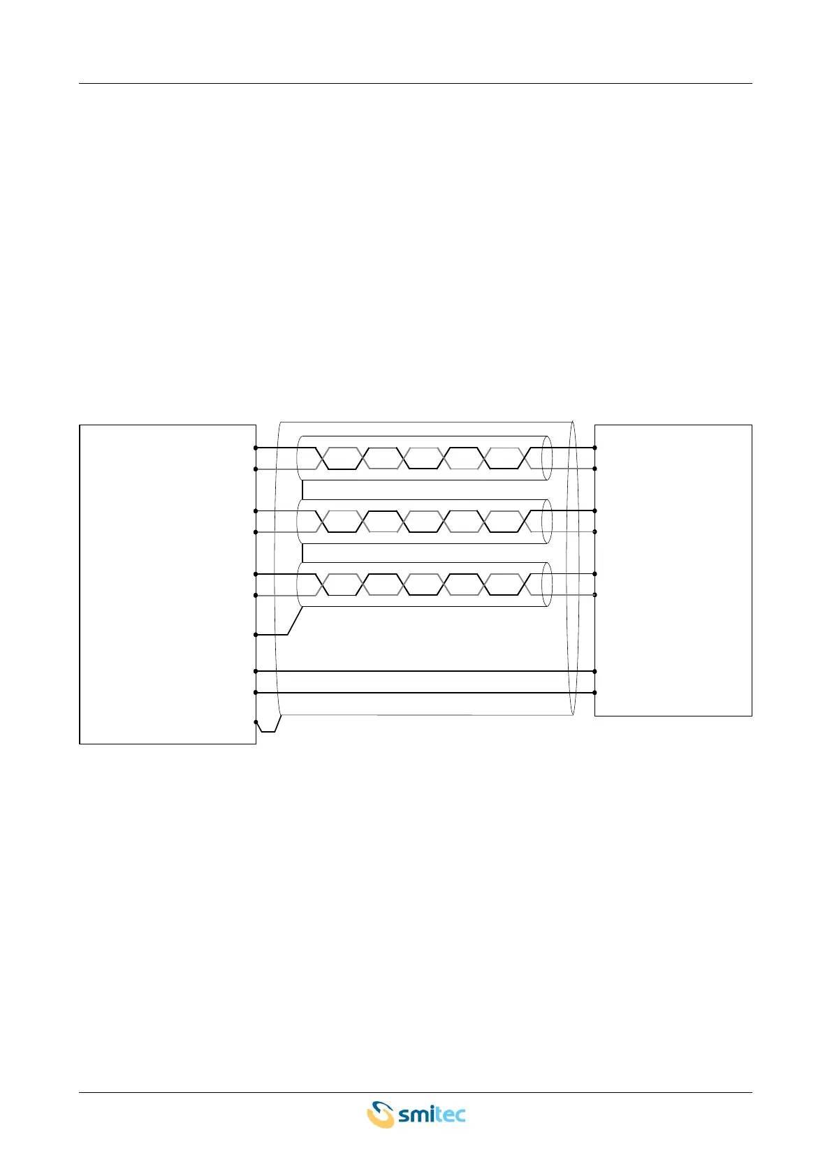
The cable to be used for the wiring must be shielded; the wiring must be made with three pairs of twisted
conductors; each pair must be individually shielded. The internal shields must be earthed (GND, pin 1 on the
connector), while the external shield must be earthed only on the servo-drive side, through the connector
metal shell.
The resolver sends analogue signals, which are prone to electrical interference. Make sure the cable is
positioned far away from noise sources (such as power cables, inverters, switching power supplies,
contactors, motors, etc.). In case of excessive interference in the feedback signal, the motor may behave
uncontrollably.
The recommended connection scheme for the resolver is shown in the following picture:
Ver. 1.09 SMITECdd 53/74