Servodrives / inverters series COSMOS 301X Installation, use and maintenance manual - EN
5.6 Motor, brake resistor and DC bus wiring
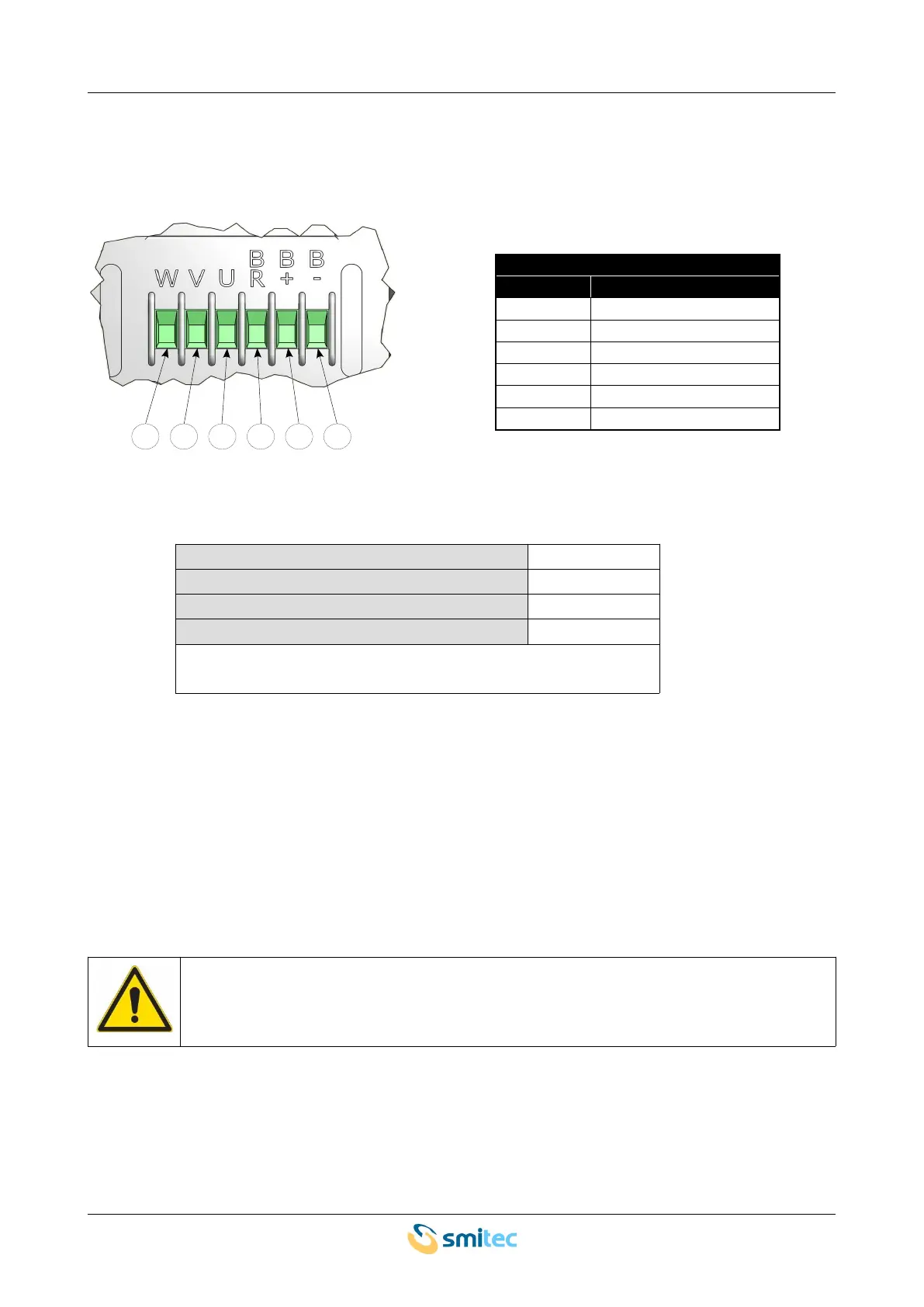
The power wiring must be made by means of a 6-pole terminal board; the following picture shows the pin
configuration.
Motor, brake resistor and DC bus
label signal
W Motor output – phase W
V Motor output – phase V
U Motor output – phase U
BR Brake resistor output
B+ Bus voltage - positive
B- Bus voltage - negative
Here are the specifications of the cables to be used for wiring:
Minimum cross-section of solid conductor * ** 0.75 mm
2
Maximum cross-section of solid conductor * ** 2.5 mm
2
Minimum cross-section of flexible conductor * ** 0.75 mm
2
Maximum cross-section of flexible conductor * ** 2.5 mm
2
*= Use 60/75 °C wires only (UL)
**= Use Copper Conductors only (UL)
The terminal board contacts must be tightened by means of a flat-blade screwdriver (blade width: 3.5 mm) or
by means of a cross-head screw-driver (PH 0); the recommended tightening torque is 0.55 Nm ±10%.
The conductor section size depends on the maximum current; in case of installation in the electrical panel of
a machine, please consider that the EN 60204-1 Standard does not allow the use of cables with a cross-
section smaller than 0.75 mm
2
inside the housings and 1.0 mm
2
outside (0.75 mm
2
for multicore cables). To
connect the motor, a shielded multicore cable with a cross-section of 0.75 mm
2
may be an excellent choice in
most applications.
The conductors cross-section for connecting bus and brake resistor voltages must be large
enough to handle the maximum short-circuit voltage on the power terminals of the servo-
drive.
The motor must be connected as shown in the following picture:
Ver. 1.09 SMITECdd 37/74