Servodrives / inverters series COSMOS 301X Installation, use and maintenance manual - EN
5.7.5 Connections (KZ010387 and KZ010388)
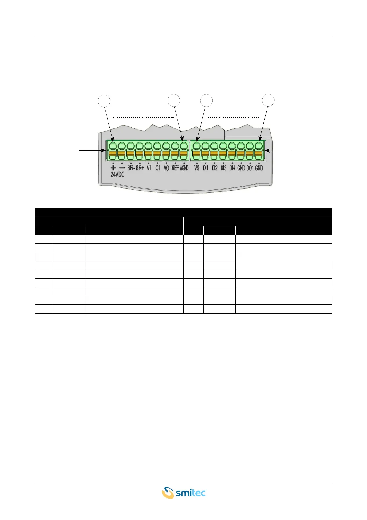
This version is equipped with two removable connectors (J5 and J6) for wiring digital/analogue I/Os.
Unlike other versions, 24V auxiliary power is used only for motor braking; the control logic is powered directly
from the 230 VAC mains. Here is the pin configuration of the connectors:
24V and I/O power
connector J5 connector J6
pin label signal pin label signal
1 24VDC + 24VDC power – positive side 1 VS 24V power for sensors
2 24VDC - 24VDC power – negative side 2 DI1 digital input #1
3 BR- Motor brake output – negative side 3 DI2 digital input #2
4 BR+ Motor brake output – positive side 4 DI3 digital input #3
5 VI
0 to 0 V input
5 DI4 digital input #4
6 CI
4 to 20mA input
6 GND earth on analogue I/Os
7 VO
0 to 10 V output
7 DO1 digital output #1
8 REF 10V reference voltage output 8 GND earth on analogue I/Os
9 AGND earth on analogue I/Os
Ver. 1.09 SMITECdd 45/74
J6
J5
1
8
1
9
1
9
1
8