Servodrives / inverters series COSMOS 301X Installation, use and maintenance manual - EN
5.8 Field bus
5.8.1 FLEXTRON versions
These versions of servo-driver/inverter are equipped with an interface for FLEXTRON field bus. This bus,
based on a RS485 electrical non-insulated interface, performs a reliable, real-time control of complex
applications.
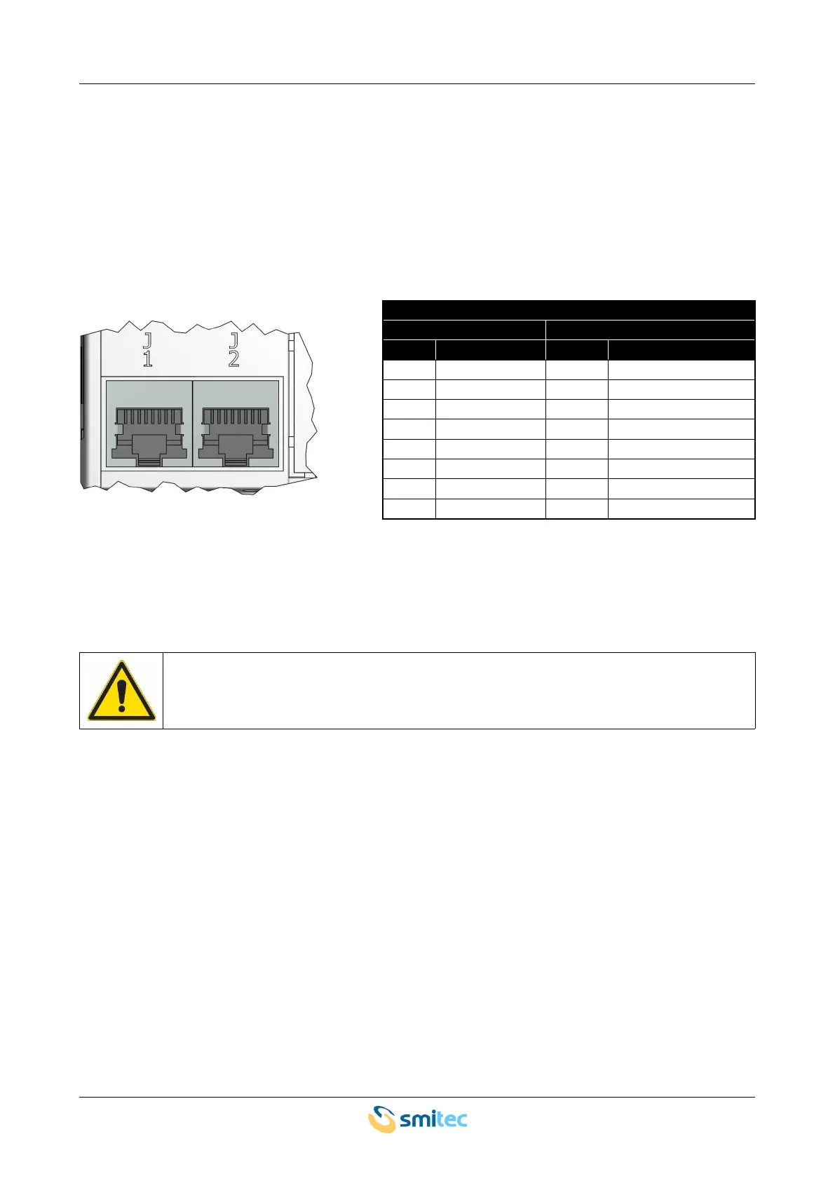
The connections are made by means of RJ45 connectors, situated on the front panel; the following picture
indicates the pin configuration.
FLEXTRON field bus
connector J1
connector J2
pin signal pin signal
1 DATA+ 1 DATA+
2 DATA- 2 DATA-
3 GND 3 GND
4 Internal use 4 Internal use
5 Internal use 5 Internal use
6 NC 6 NC
7 Internal use 7 Internal use
8 Internal use 8 Internal use
The servo-drives equipped with FLEXTRON field bus implement a mechanism of automatic address setting:
each device receives a progressively increasing address, according to the electric position of the slave.
This is to say that the devices create a chain, starting from the master and finishing at the last slave; the
addresses follow the same order.
Do not change the devices wiring order in a FLEXTRON bus, otherwise the system may
behave uncontrollably; risk of damages to persons and/or property.
FLEXTRON devices implement an automatic termination system; this is to say that the last device in the
chain automatically inserts a termination resistor, in order to prevent reflections on the transmission line.
Ver. 1.09 SMITECdd 59/74