Servodrives / inverters series COSMOS 301X Installation, use and maintenance manual - EN
5.7.14 0 to 10V analogue input and 10V reference generator
Some versions of the servo-drive/inverter are equipped with an analogue input stage for 0 to 10V signals.
Since potentiometers and potentiometer-type position sensors are commonly used, a fixed 10V voltage is
generated for polarizing them.
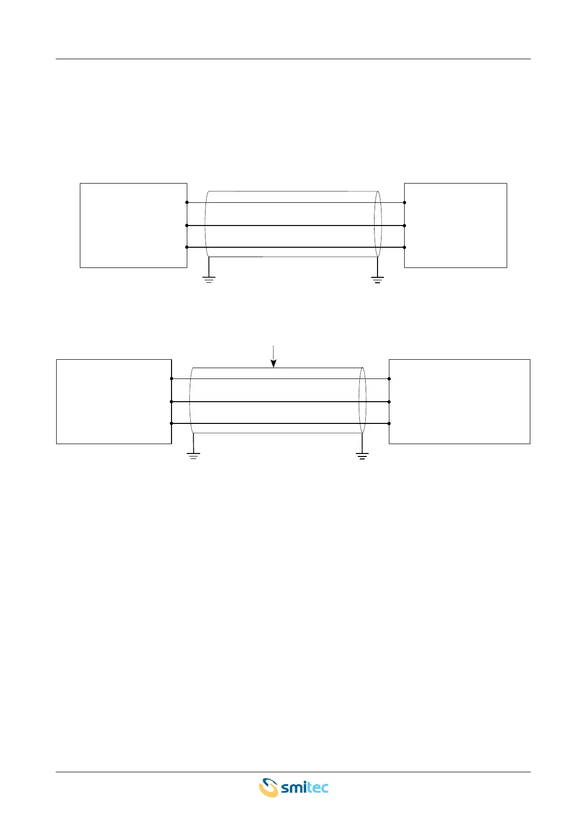
The recommended connection scheme for a sensor is shown in the following picture:
A potentiometer, on the other hand, is connected as follows:
In both cases, it is recommended to use shielded cables for the connections.
Be careful about the analogue signal wiring, if these signals are used as reference signals for motor speed or
motor position. In case of excessive interference, the motor may behave uncontrollably; position the cable far
away from sources of noise (such as power cables, inverters, switching power supplies, contactors, motors,
etc.).
Ver. 1.09 SMITECdd 55/74