Wire EDM Machine Operation Chapter 12
Copyright November, 98 Page 12-12 Sodick Inc.
AWT U AND V ALIGNMENT PROCEDURE
For the AWT to thread correctly, the U & V axis must move to align the water jet to the
lower wire guide. This offset is calculated by the following procedure.
Remove the lower flange and flushing nozzle.
2) Set the upper head to the cutting position, then move the AWT pipe all the way
down (A320D) and to about .5" above the lower wire guide on all other machines.
3) Go to “MAL”, “MDI” and flip the switch on the control to W. (turns on water
jet).
4) Jog the U&V axis until the jet is centralized in the funnel in the lower guide.
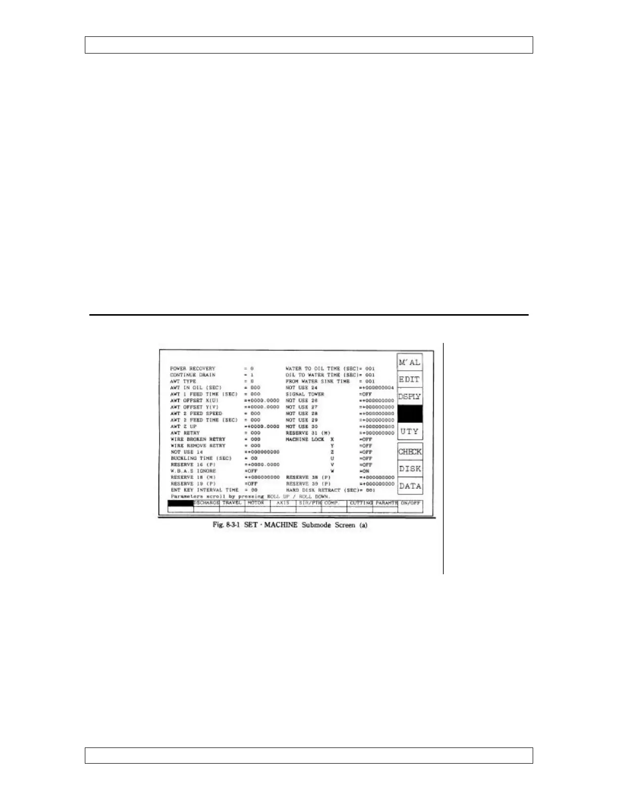
5) Enter the numbers in the U&V display into the “SET”, “MACHINE” screen,
parameter “AWT OFFSET XY (UV)”.
6) Highlight “MAL”, “MDI” and type UV and press enter to return the U&Vaxis
to zero.
“
“
S
S
E
E
T
T
”
”
“
“
M
M
A
A
C
C
H
H
I
I
N
N
E
E
”
”
S
S
U
U
B
B
M
M
O
O
D
D
E
E
S
S
C
C
R
R
E
E
E
E
N
N
Figure 12-3 AWT Parameters screen