Wire EDM Machine Operation Chapter 15
Copyright November, 98 Page 15-7 Sodick Inc.
E
E
D
D
I
I
T
T
,
,
G
G
R
R
A
A
P
P
H
H
S
S
C
C
R
R
E
E
E
E
N
N
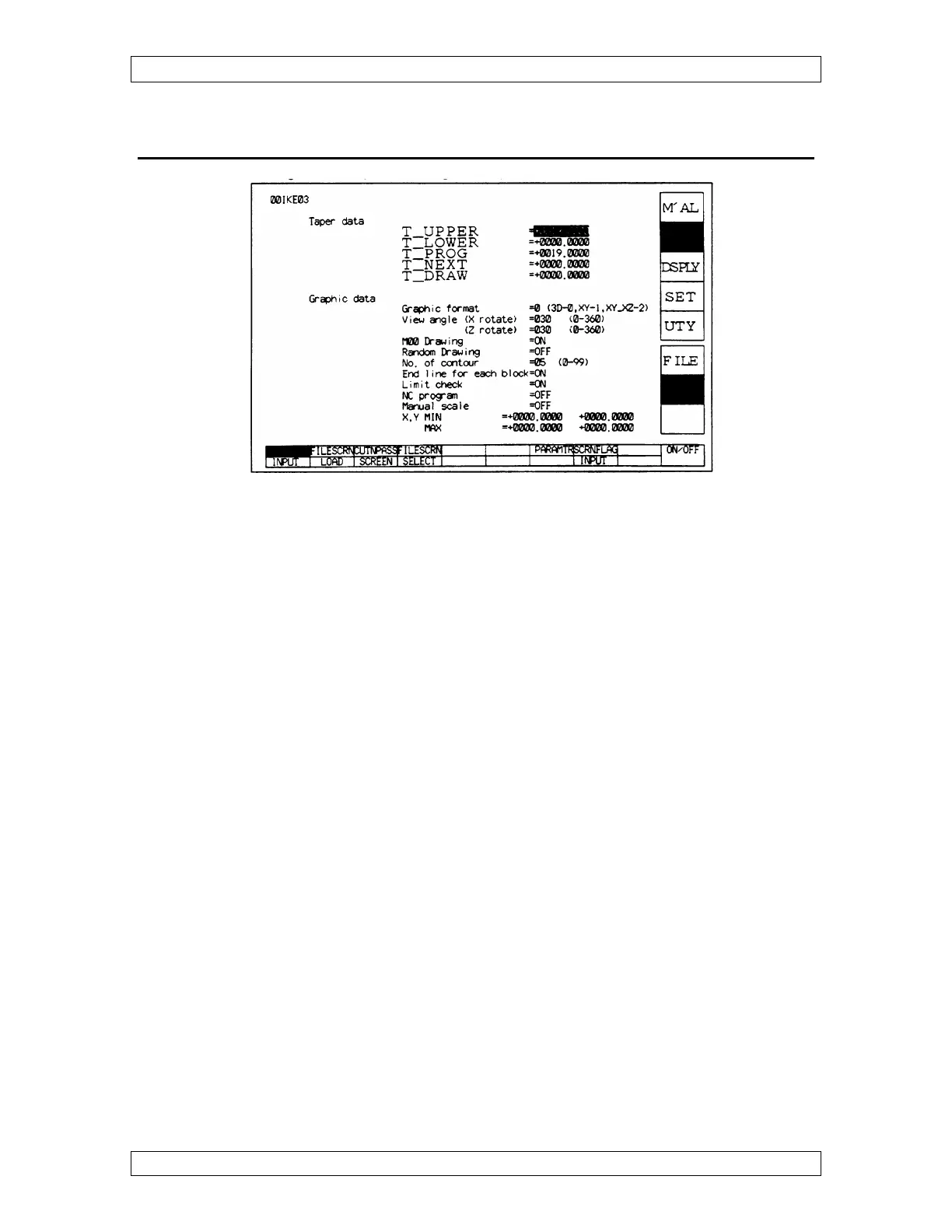
When you go to EDIT, GRAPH, CUT N PASS and you get the error message same data
are set in Taper Data TP & TN, you will have to enter either 0 or Workpiece Thickness
in table to Next under Taper Data when in Graphics. Now try to do a CUT N PASS
again.
NOTE: Graphics drawing will show the TOP of the part as BLUE, and the
BOTTOM of the part as GREEN.
GRAPHIC FORMAT: Choose 0 for 3D, 1 for Top view or 2 for a Front & Top view.
VIEW ANGLE: Usually both X rotate and Z rotate at 30°. This specifies the angle of
rotation of Graphics in X & Z axis, when in 3D.
M00 DRAWING: Shows where your stop is located when ON.
RANDOM DRAWING: When in 3D, it shows only a single plane, usually OFF.
NO. OF CONTOURS: When in 3D, how many slices through thickness of part. This
controls the resolution of the picture.
END LINE FOR EACH BLOCK: When on, the graphics drawing will show red lines
at the end of each block of NC .
LIMIT CHECK: When ON, it will tell you if the machine will hit a limit switch, when
running the program. This does not replace dry run. Remember to be at the start point
before graphing the program.