Wire EDM Machine Operation Chapter 3
Copyright November, 98 Page 3-2 Sodick Inc.
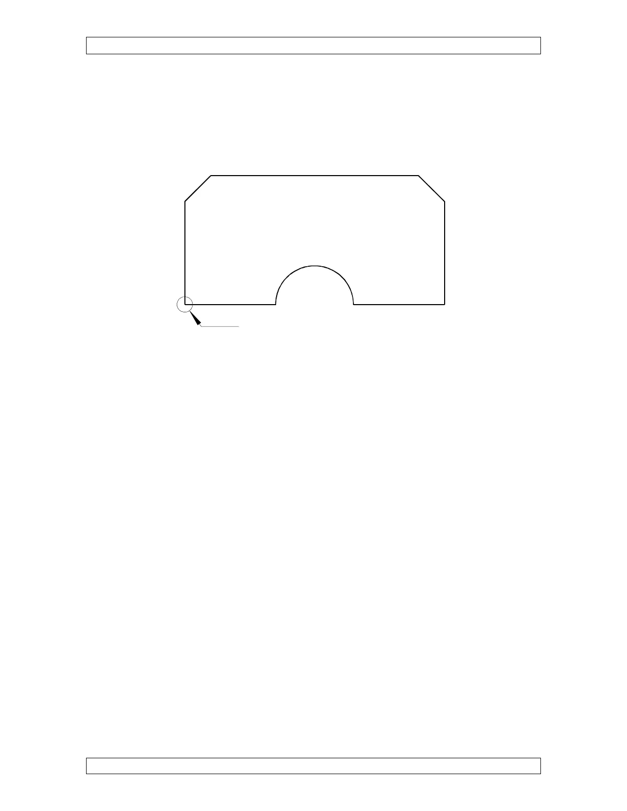
Notice that all dimensions on Figure 3-1 come from the lower left corner of the part.
Since this is the case, the lower left hand corner of the part would make an excellent point
at which to place the program zero point. Figure 3-2 illustrates this.
Figure 3-2
Also, it is a very good idea to mark up your print to show the location of the program
zero point and wire start point so that you can keep track of what you are doing. Another
point about program zero: Coordinates that go into your programs will be including a
minus direction. The plus sign (+) is assumed, meaning you can omit it when
programming positive values. But the minus sign (-) is required for negative coordinates.
Positions to the right of program zero in X and above program zero in Y are considered
to be plus. Positions to the left of program zero in X and below program zero in Y are
considered to be minus (-).
We should point out one thing about determining plus and minus for X and Y. Think
about the wire actually moving in X and Y. In reality, the TABLE is actually causing the
X and Y motion. This means that to cause the wire to move to the right (X+), the table
actually has to move to the left. Think of the WIRE movement and you will not get
confused.