7
Product Overview
2.5 Working Principle
2.5.1 Circuit Diagram
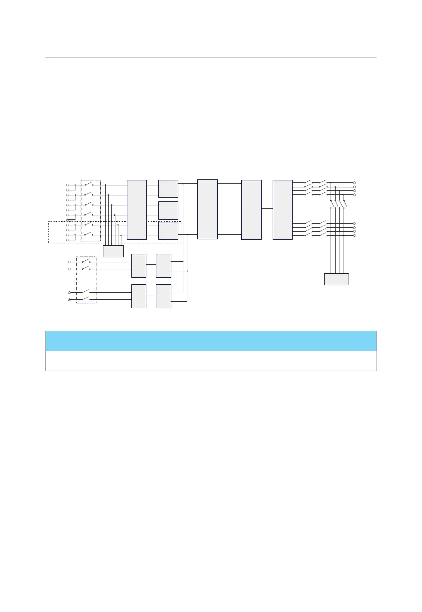
The inverter is equipped with multi-channel MPPT for DC input to ensure maximum power
even under different photovoltaic input conditions. The inverter unit converts DC into
AC that meets the requirements of the power grid and feeds it into the power grid. The
principle design of inverter is shown in the figure below:
PV EMI
Filter
MPPT 1
MPPT 2
MPPT 3
DC Bus
Inverter
Circuit
DC/AC
INV EMI
Filter
DC SPD
BAT 1
EMI
Filter
BAT 1
Circuit
BAT2
EMI
Filter
BAT 2
Circuit
DC Switch
AC SPD
PV1+
PV1-
PV2+
PV2-
PV3+
PV3-
BAT1+
BAT1-
BAT2+
BAT2-
EPS L1
EPS L2
EPS L3
EPS N
Grid L1
Grid L2
Grid L3
Grid N
Figure 2-5 Circuit Diagram for X3-ULTRA series inverter
NOTICE!
• MPPT 3 is available for X3-ULT-15KP, 20KP, 25K and 30K inverter.
 Loading...


