63
Electrical Connection
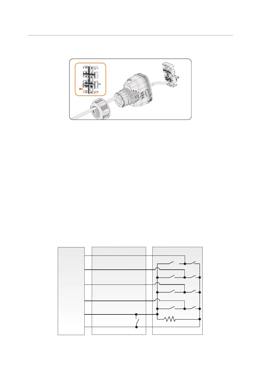
Step 4: Install the network cable to RS485 of cable fixture according to the labeling.
Figure 8-42 Installing RJ45 terminal to the cable fixture
Step 5: Connect the assembled connector to COM 1 terminal. Make sure the cable fixture
tongue is well inserted into the slot of terminal. You will hear an audible "Click"
if it is connected securely. Lightly pull the cable backward for double check its
connection.
Step 6: Secure the assembled connector on COM 1 terminal.
a. Install the connector enclosure back into the COM 1 terminal.
b. Install the cable support sleeve into the enclosure.
c. Tighten M3 screw to secure it. (Torque: 0.4 ± 0.1 N·m)
d. Clockwise tighten the swivel nut to finish the COM 1 wiring connection.
8.6.5 DRM Connection (Applicable to AS/NZS 4777)
According to Australia AS 4777.2, the inverter needs to support the function of demand
response mode (DRM). DRM 0, DRM 1 and DRM 5 are available now.
DRM
DRM 1/5
DRM 2/6
DRM 3/7
DRM 4/8
+3.3V_COM
COM/DRM0
DRED
S5 S1
S6
S7
S8
15K
S9
S0
S2
S3
S4
Figure 8-43 DRED wiring diagram
 Loading...


