57
Electrical Connection
8.6.2 Parallel Communication Connection
The inverter provides the parallel connection function. One inverter will be set as the “Master
inverter” to control the other "Slave inverters" in the system.
NOTICE!
• The communication cable length between two parallel inverters should not exceed
10 meters, and the total cable length of all parallel inverters should not exceed 80
meters.
Table 8-4 Maximum number of inverter parallelled
Application
X3-
ULT-
15KP
X3-
ULT-
15K
X3-
ULT-
19.9K
X3-
ULT-
20K
X3-
ULT-
20KP
X3-
ULT-
25K
X3-
ULT-
30K
With X3-Parallel
EPS BOX
10 10 7 7 7 6 5
Without X3-
Parallel EPS BOX
3
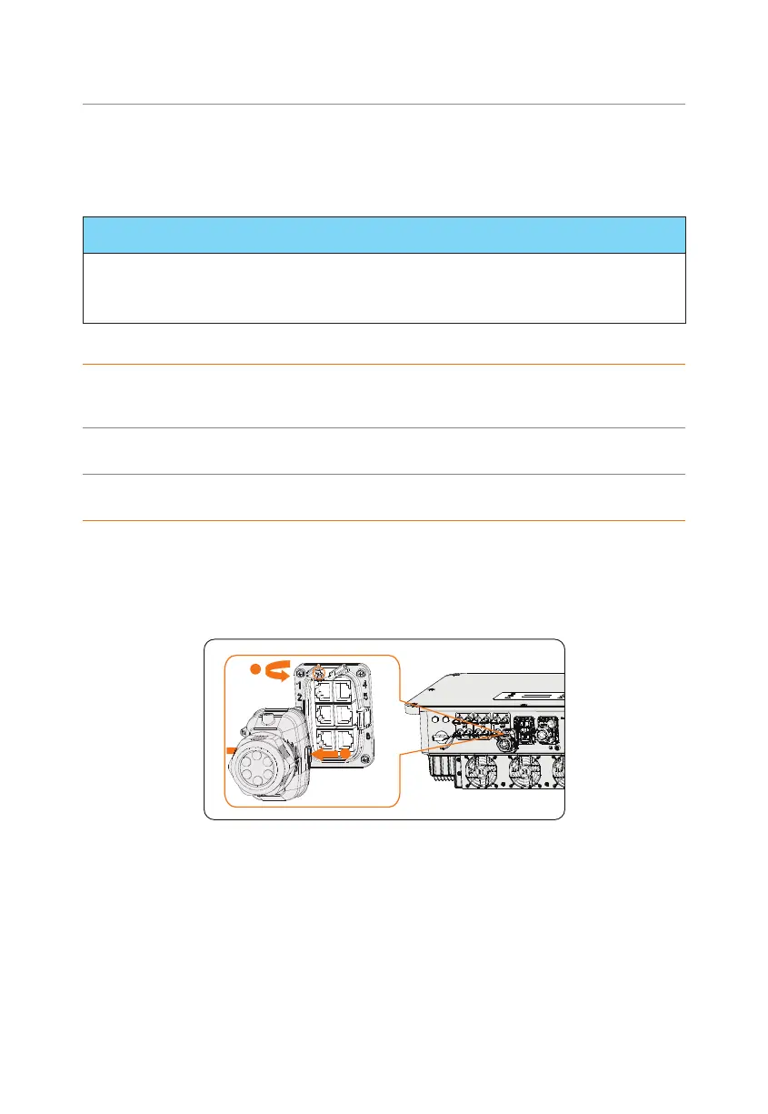
Parallel connection wiring procedure
Step 1: Loosen the screws on the COM 1 terminal. Pinch the tabs on the sides of the
COM 1 connector enclosure and pull it at the same time to disassemble it.
1
2
Figure 8-32 Removing the connector enclosure
Step 2: Anti-clockwise loosen the swivel nut and pull out the sealing plugs. Keep them
still in the cable support sleeve if you choose not to connect the cable.
 Loading...


