26
Preparation before Installation
NOTICE!
• Please take the weight of battery into account when wall-mounting the whole
system.
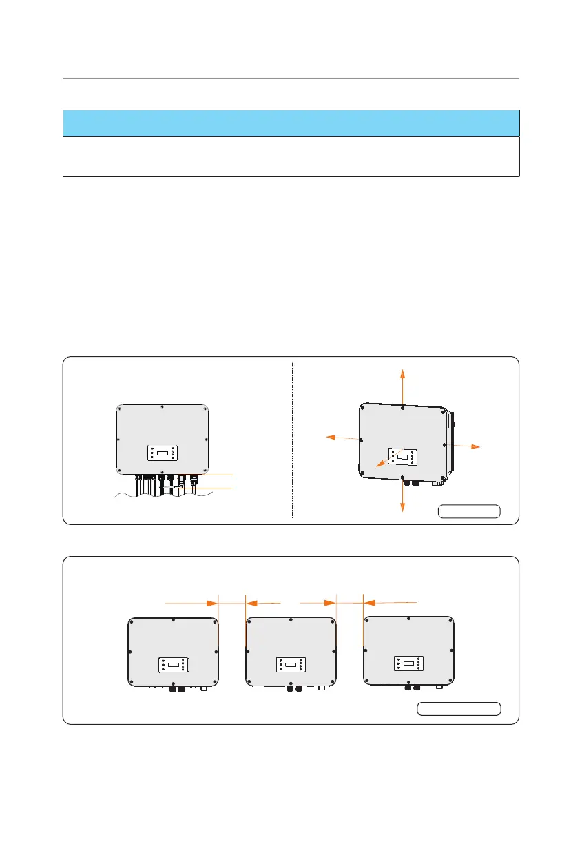
5.1.3 Clearance Requirement
The minimum clearance reserved for the connected terminal at the bottom of inverter
should be 10 cm. When planning installation space, it is important to simultaneously
consider the bending radius of the wires.
To guarantee proper heat dissipation and ease of disassembly, the minimum space around
the inverter must meet the standards indicated below.
For installations with multiple inverters, make sure to leave a minimum space of 30 cm
between each inverter. In areas with high ambient temperatures, increase the clearances
between the inverters and provide adequate fresh air ventilation if feasible.
Single inverter
≥30 cm
≥30 cm
≥30 cm
≥30 cm
≥30 cm
10 cm
Figure 5-4 Clearance requirement for single inverter
Multiple inverters
≥30 cm
≥30 cm
Figure 5-5 Clearance requirement for multiple inverter
 Loading...


