64
Electrical Connection
Table 8-5 Desciptions of DRM
Mode Pin location Requirement
DRM 0 Pin 6
When S0 is closed, the inverter shuts down.
When S0 is open, the inverter resumes grid connection.
DRM 1 Pin 1
When S1 is closed, the inverter does not input active
power.
DRM 5 Pin 1
When S5 is closed, the inverter does not output active
power.
DRM connection wiring procedure
Step 1: Loosen the screws on the COM 1 terminal. Pinch the tabs on the sides of the
COM 1 connector enclosure and pull it at the same time to remove it.
Step 2: Anti-clockwise loosen the swivel nut and pull out the sealing plugs. Keep them
still in the cable support sleeve if you choose not to connect the cable.
Step 3: Thread the cable through the swivel nut, cable support sleeve, and connector
enclosure in sequence.
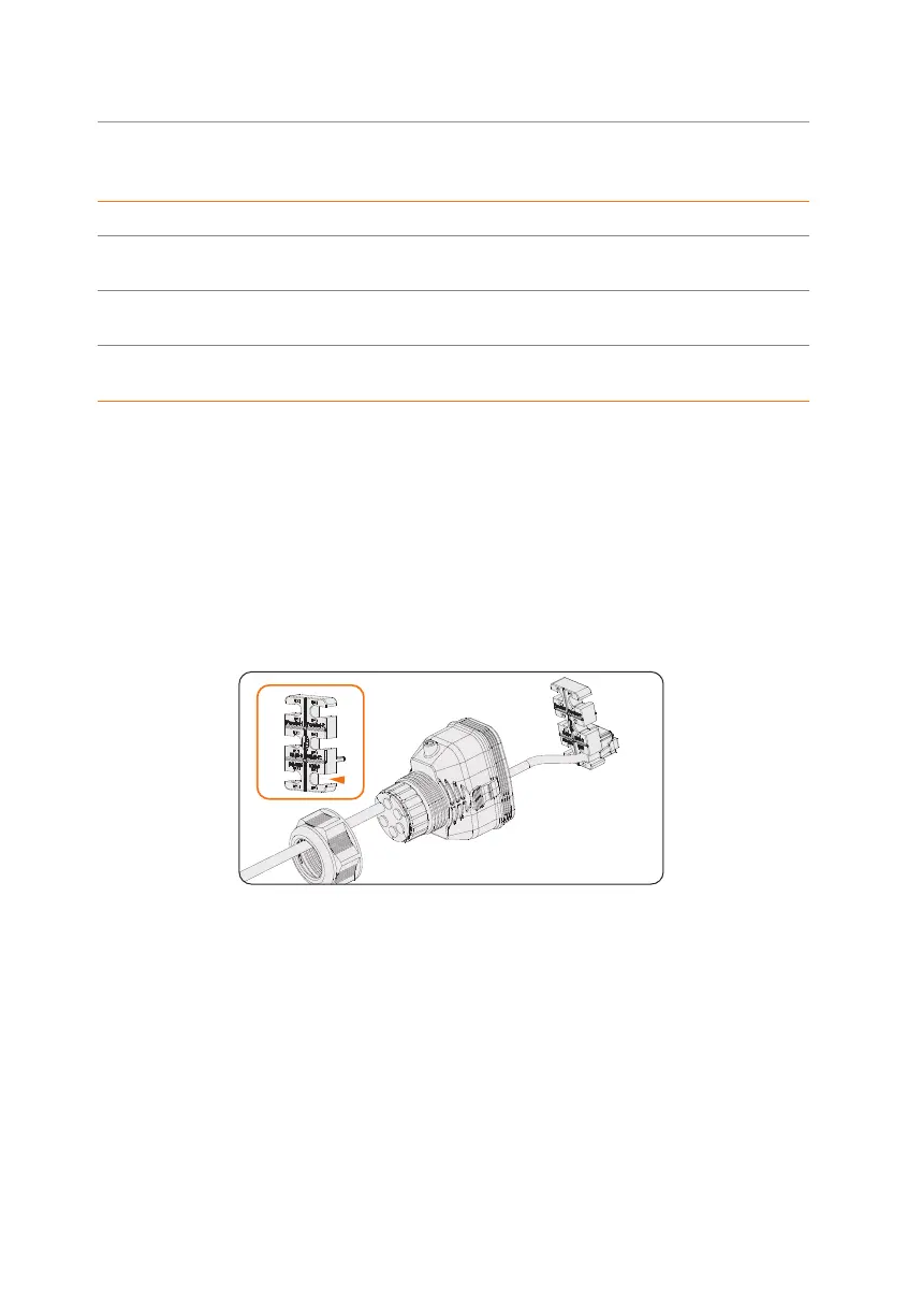
Step 4: Install the network cable to RS485 of cable fixture according to the labeling.
Figure 8-44 Installing RJ45 terminal to the cable fixture
Step 5: Connect the assembled connector to COM 1 terminal. Make sure the cable fixture
tongue is well inserted into the slot of terminal. You will hear an audiable "Click"
if it is connected securely. Ligthtly pull the cable backward for double check its
connection.
Step 6: Secure the assembled connector on COM 1 terminal.
a. Install the connector enclosure back into the COM 1 terminal.
b. Install the cable support sleeve into the enclosure.
c. Tighten M3 screw to secure it. (Torque: 0.4 ± 0.1 N·m)
d. Clockwise tighten the swivel nut to finish the COM 1 wiring connection.
 Loading...


