85
Operation on LCD
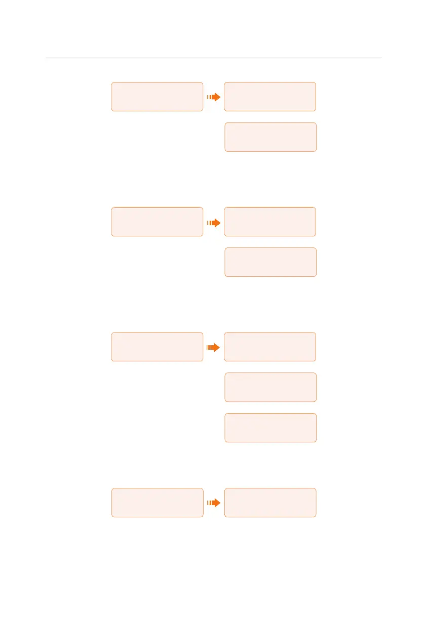
====System Status====
>Battery1
Battery2
======Battery1=======
>U 0.0V
I 0.0A
P 0W
======Battery1=======
SoC 0%
Cell Temp 20
℃
BMS Connected
• On-grid status: Information contains the voltage, current, frequency, and output
power of Grid terminal. The "A", "B" and "C" in On-grid A, On-grid B and On-grid
C refers to L1, L2 and L3 respectively. The figure below will take On-grid A as an
example.
====System Status====
>On-Grid
EPS
======On-grid A======
>Ua 0.0V
Ia 0.0A
PaOut 0W
======Frequency======
Fa 0.00Hz
Fb 0.00Hz
Fc 0.00Hz
• EPS status: Information contains apparent power, voltage, current, active power
and frequency of EPS terminal when it is disconnected from the grid. The "A", "B"
and "C" in EPS A, EPS B and EPS C refers to L1, L2 and L3 respectively. The figure
below will take EPS A as an example.
====System Status====
>EPS
Meter/CT
=====EPS_Spower=====
>PaS 0.0W
PbS 0.0W
PcS 0.0W
=======EPS A=======
Ua 0.00V
Ia 0.00A
PaActive 0.00W
======Frequency======
Freq
0.00Hz
• Meter/CT status: Information contains feed-in power of L1, L2 and L3 detected
by the connected meter or CT. "+" represents feeding electricity to the grid, "-"
represents drawing electricity from the grid (buying electricity).
====System Status====
EPS
>Meter/CT
=====Meter/CT=====
>Pfeedin A 0.0W
Pfeedin B 0.0W
Pfeedin C 0.0W
 Loading...


