17
Product Overview
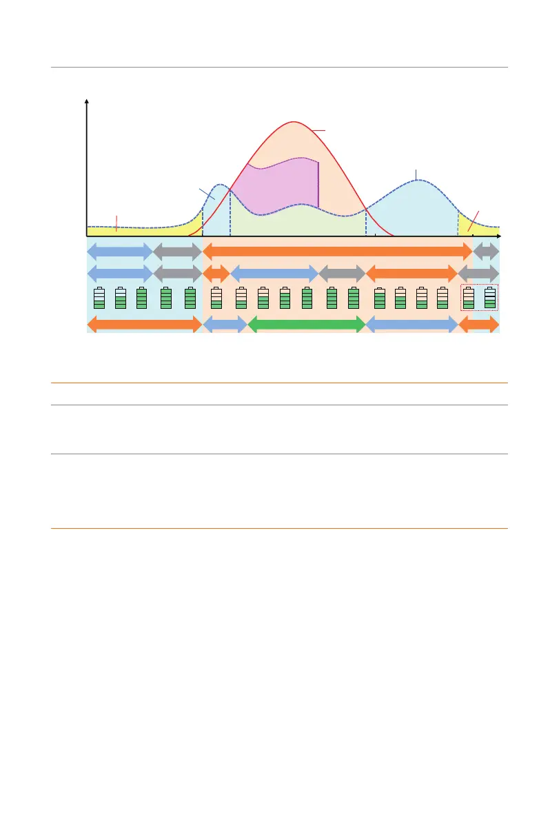
Backup Mode
(Assu min g p eak p ower from 7:00 to 23: 00)
7:00
Th e g rid su p plies p ower to
th e lo a d an d cha rges the
battery
23: 001 8 : 0 0
PV p o wers the load
Charg e the b attery
Load po w er cu rve
Forced ch a rg in g tim e
Chag ring
Pu rch ase electricity
Oth er
Stan d by
Allowed disch arg ing p eriod
Disc harging Chag ring Stan d by Discharg ing
Oth er
Stan d by
Sell electricity
Self use Self use
Pu rch ase
electricity
Power
Time Line
Ba ttery
status
Ba ttery
SO C
Pu rch ase
status
Time
settin g
PV an d b attery p ower th e lo a d
PV an d b attery
pow er lo ad
Su rp lu s will b e
so ld to th e u tility
PV input power
Idea: B a sed o n the Self u se mod e, th e m in im u m
SO C is increased to prep are fo r a p o w er o u ta g e.
Reserve en oug h
ca p acity to en ter
O-grid mod e in
ca se o f p o wer
fa ilure
Figure 2-14 Backup mode
Table 2-5 Description of backup mode
Time period Inverter working status
Forced charging
period
• Charge the battery firstly untill the battery SOC reaches the
specified Charge battery to value. You can configure the
inverter to either draw power from the grid or not.
Allowed discharging
period
• The working logic remains the same as for self-use mode, but
it enters a standby state when there is no PV input and the
battery SOC reaches Min SOC (on-grid min SOC). During this
time, in the event of a grid outage, it will switch to EPS mode
until the battery discharges to Min SOC (Off-grid min SOC).

 Loading...


