63
Electrical Connection
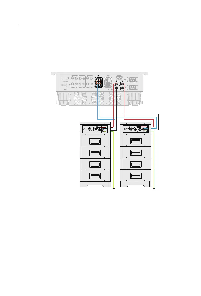
7.6.3 BMS Communication Connection
Through BMS-1 and BMS-2 communication terminal, two models of batteries can be
communicated with inverter.
BMS connection diagram
*For detailed connection
on the battery side, please
see documentation of the
battery manufacturer.
Figure 7-41 BMS connection diagram
BMS wiring procedure
Step 1: Loosen the screws on the COM 1 terminal. Pinch the tabs on the sides of the
COM 1 connector enclosure and pull it at the same time to remove it.
Step 2: Anti-clockwise loosen the swivel nut and pull out the sealing plugs. Keep them
still in the cable support sleeve if you choose not to connect the cable.
Step 3: Thread the cable through the swivel nut, cable support sleeve, and connector
enclosure in sequence.
Step 4: Install the network cables to BMS-1 and BMS-2 of cable fixture according to the
labeling.

 Loading...


