66
Electrical Connection
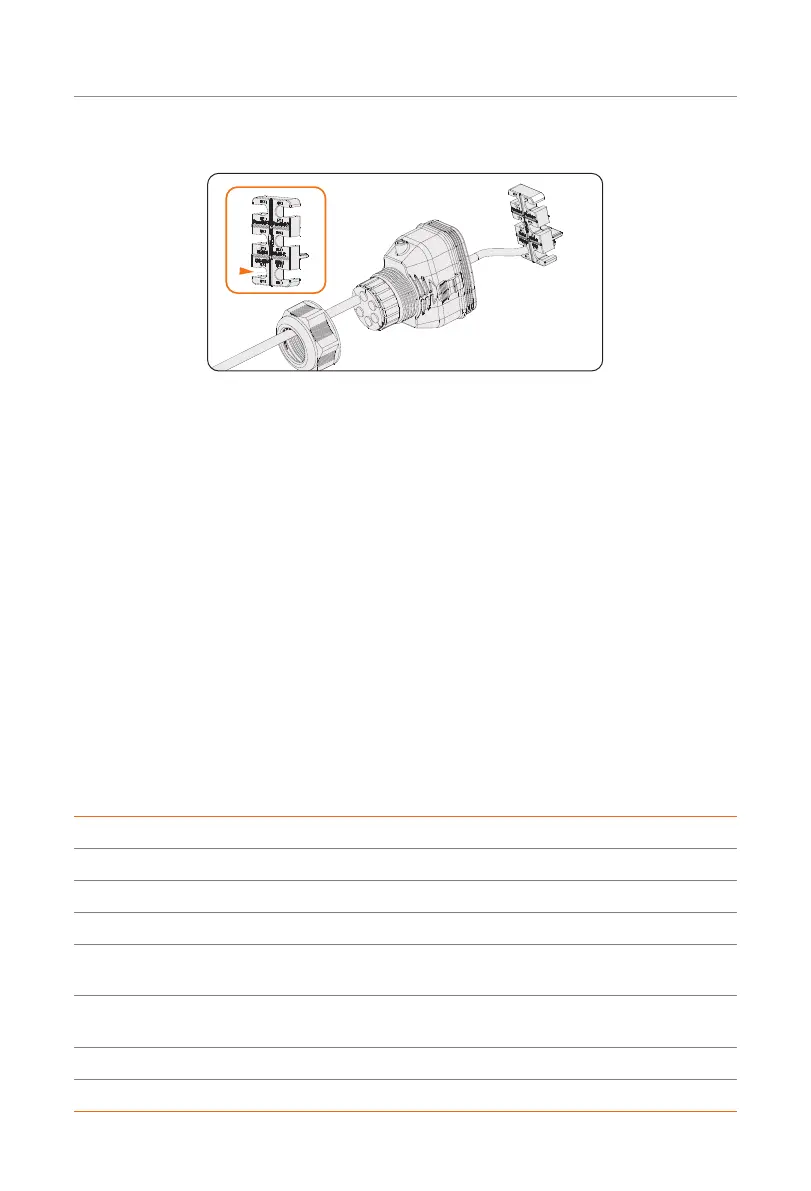
Step 4: Install the network cable to RS485 of cable fixture according to the labeling.
Figure 7-45 Installing RJ45 terminal to the cable fixture
Step 5: Connect the assembled connector to COM 1 terminal. Make sure the cable fixture
tongue is well inserted into the slot of terminal. You will hear an audiable "Click"
if it is connected securely. Ligthtly pull the cable backward for double check its
connection.
Step 6: Secure the assembled connector on COM 1 terminal.
a. Install the connector enclosure back into the COM 1 terminal.
b. Install the cable support sleeve into the enclosure.
c. Tighten M3 screw to secure it. (Torque: 0.6 ± 0.1 N·m)
d. Clockwise tighten the swivel nut to finish the COM 1 wiring connection.
7.6.5 DRM Connection (Applicable to AS/NZS 4777)
According to Australia AS 4777.2, the inverter needs to support the function of demand
response mode (DRM). DRM 0, DRM 1 and DRM 5 are available now. Therefore, connect
Pin 1, Pin 6 and Pin 7 when connection.
Table 7-5 Desciptions of DRM
Mode Requirement
DRM 0 Operate the disconnection device.
DRM 1 Do not consume power.
DRM 2 Do not consume at more than 50% of rated power.
DRM 3
Do not consume at more than 75% of rated power and source reactive
power if capable.
DRM 4
Increase power consumption (subject to constraints from other active
DRMs).
DRM 5 Do not generate power.
DRM 6 Do not generate at more than 50% of rated power.

 Loading...


