75
Electrical Connection
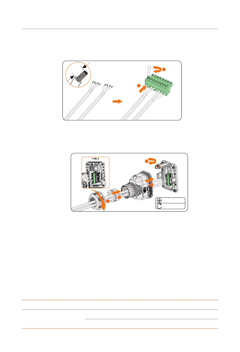
Step 3: Strip approx.6 mm of the cable insulation. Insert the conductors into the 8-pin
terminal block and tighten the terminal screws. (torque: 1.5 N·m.) Ensure that the
conductors are firmly seated in the terminal.
Four-core
Four-core
6 mm
1
2
Figure 7-58 Connecting to 8-pin terminal block
Step 4: Connect the assembled communication cable into the COM 2 terminal. Lightly
pull the cable backward to confirm tight insertion and then install the connector
back.
1
2
4
3
M3
0.6 ± 0.1 N·m
Figure 7-59 Connecting to the inverter
7.7.4 DIO Communication Connection
DIO terminal is designed to communicate with generator and system switch through dry
contact.
To enhance safety and reduce the risk of injury, you can install the system switch in a
readily accessible location through dry contact connection. In the event of an emergency,
the system switch can be easily reached and pressed to promptly switch off the entire
system, ensuring a swift response and preventing further harm.
For generator, please refer to "14.1 Generator Application" for specific application.
DIO pin definition
Application Pin Pin assignment
For generator dry contact
output
1 DO_1
2 DO_2

 Loading...


