76
Electrical Connection
For system switch dry
contact input
3 DI_1+
4 DI_1-
Reserved
5 DI_2+
6 DI_2-
Reserved 7 GND_COM
NOTICE!
• If there is strong interference in the surroundings, it is recommended to use shielding
cables and ground the shielding layer of the cables.
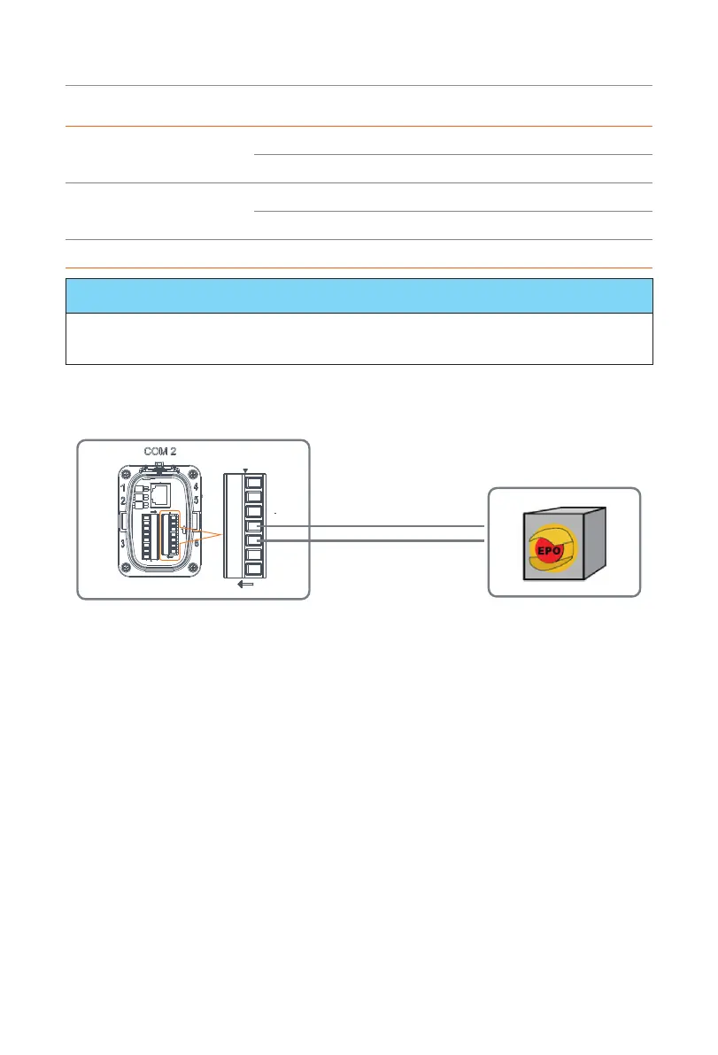
System switch connection diagram
System switch
DIO terminal
Pin 4
Pin 3
Communication
Figure 7-60 System switch connection diagram
Choose a self-locking switch for the system. When system switch is pressed, OFF MODE
(DIO SW) will be displayed on the LCD screen and the system will be powered off. To
release the switch, press it again.
DIO wiring procedure
Step 1: Loosen the screws on the COM 2 terminal. Pinch the tabs on the sides of the
COM 2 connector enclosure and pull it at the same time to remove it.
Step 2: Loosen the swivel nut and pull out the sealing plugs. Keep them still in the cable
support sleeve if you choose not to connect the cable.
Step 3: Prepare two four-core signal cable. Trim the excess one core wire. The cut core
wire should be insulated. Thread the cables through the swivel nut, cable support
sleeve, and connector enclosure in sequence.
Step 4: Stip approx.6 mm of the cable insulation. Insert the conductors into the 7-pin
terminal block and tighten the terminal screws. (torque: 1.5 N·m.) Ensure that the
conductors are firmly seated in the terminal.

 Loading...


