70
Electrical Connection
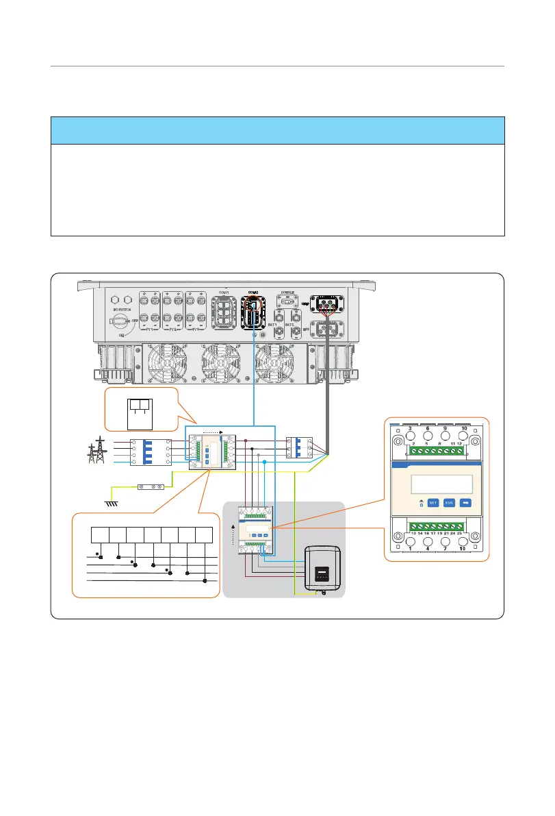
Meter/CT Connection Diagram
NOTICE!
• The following figures take inverter with Meter DTSU666 as an example.
• If you have other power generation equipment (such as an inverter) at home and
wants to monitor both equipment, our inverter provides Meter 2 communication
function to monitor the power generation equipment. For more information, please
contact us.
• Please make PE connection for Meter if the meter has ground terminal.
• Meter connection diagram
CT-R
RS485 on DTSU666
Meter 1
Meter 2
other power
generatation
equipment
2425
A B
RS485
Breaker
Breaker
In
Out
L1
L2
L3
N
E-BAR
Power connection on CHNT DTSU666
In
Out
Grid input Output
3 6
9
1
4
7 10
10
107641 3
L1
L2
L3
N
9
Grid
* The meter in the connection diagram is taken as an example with DTSU666.
Figure 7-47 Meter connection diagram

 Loading...


