JEA USER MANUAL
10 I +44 (1753) 214 500
3. INSTALLATION
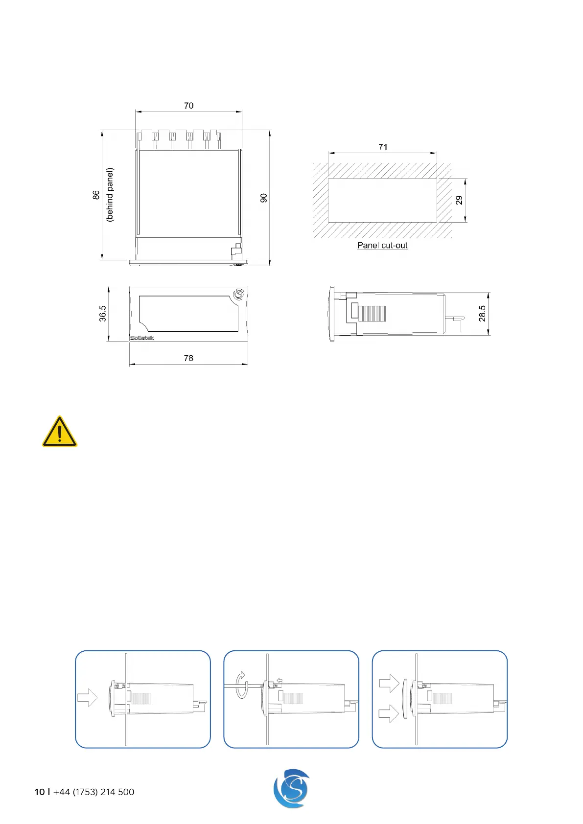
3.1 DIMENSIONS AND PANEL CUT-OUT
3.2 PANEL MOUNTING
WARNING!
Avoid installing the JEA in the following environments:
• Strong vibrations or knocks
• Exposure to continuous water spray
• Aggressive and polluting atmospheres to avoid corrosion
• Environments where explosive or mixes of flammable gases are present
1. Cut a rectangle aperture in the panel of the cooler where the display is to be located as per the panel cut diagram. Ensure
the aperture is free of burrs and sharp edges.
Note: The Maximum panel thickness must not exceed:
Front screw mounting: 1.6mm maximum with gasket and 3.6mm maximum without the gasket.
Side clip mounting: 6.6mm maximum with gasket and 8.6mm maximum without the gasket.
3.2.1 FRONT MOUNTING
2. Remove the bezel from the front of the JEA by pulling it off. Insert the JEA from the outside (front) of the panel.
3. Tighten the screws. After turning 90o the catch will come out of its slot and press onto the panel. Tighten the screw until the
front panel is secure, DO NOT over-tighten the screw.
4. Push the bezel back onto the front of the JEA.
 Loading...