JEA USER MANUAL
sollateksupport@sollatek.com I 11
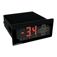
3.2.2 REAR MOUNTING
Note: Side mounting clips are purchased separately
1. Insert the JEA into the front of the panel.
2. Insert one of the side clips into the guides within the top and bottom of the body. Slide towards the front of the JEA until it is
securely against the panel. Repeat the same operation for the other side.
Note: Ensure the clips are securely attached to the JEA and are tight against the panel.
3.3 WIRING
3.3.1 OUTPUT WIRING
WARNING! MAINS CONNECTION
Risk of electrocution or damage to equipment. Ensure Mains is isolated before installation or repair of
the unit or any connected equipment.
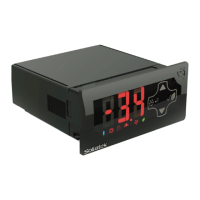
3.3.1.1 JEAx4 models
Standard Wiring (All outputs supplied with 90-300 VAC)
1. Connect the Live-In wire to terminal 3 on the JEA.
2. Connect a loop from terminal 3 (Live-In) to terminal
7, Live-2-In on the JEA.
3. Connect the Neutral wire to terminal 4 on the JEA.
4. Connect the Compressor to terminal 2 of the JEA.
5. Connect the Heater to terminal 1 of the JEA, if
required.
6. Connect the fan (Evaporator or Condenser) to
terminal 5 of the JEA, if required.
7. Connect the lights to terminal 6 of the JEA, if
required.
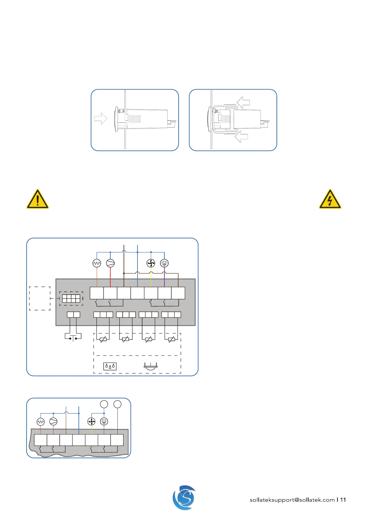
AC And DC Supply Wiring (Compressor and Heater supplied with AC, Fan and Lights supplied by DC)
1. Connect the Live-In (do not Loop to terminal 7), Neutral, Compressor, Heater,
Fan and lights as described above.
2. Connect the DC Live to terminal 7 on the JEA.
3. Connect the fan and lights to the DC Negative.
+ -+ -+-
+-+ -
16432
L in N in
5 7
P4 P3 P2 P1
1 3 5 7
2468
L2 in
Amb.
Temp
Evap.
Temp
Cond.
Temp
Air
Temp
Door
Switch
Ext. Display
FFX Expander
Connectivity
Module
PIR
Sensor
OR
Humidity
Sensor
 Loading...