JEA USER MANUAL
12 I +44 (1753) 214 500
3.3.1.2 JEAx3 Models
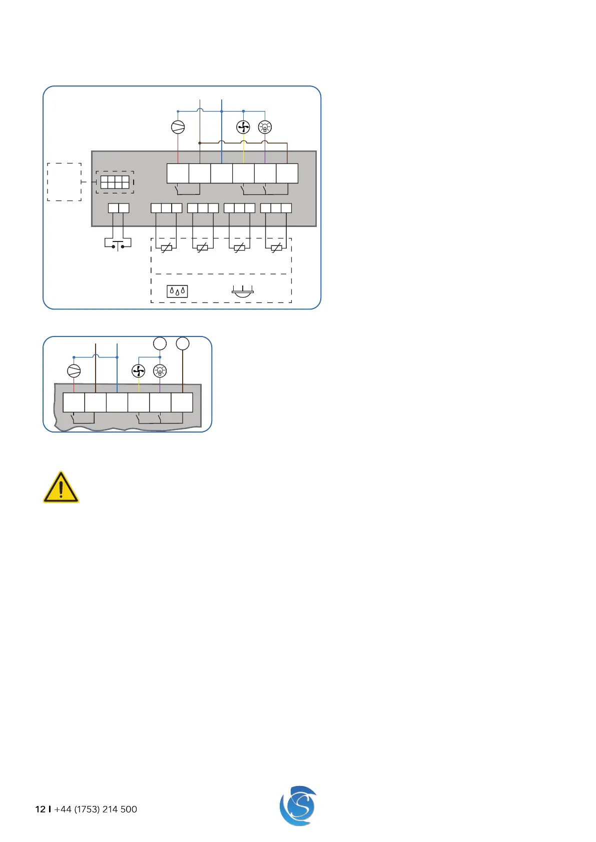
Standard Output Wiring (All outputs supplied with 90-300 VAC)
1. Connect the Live-In wire to terminal 2 on the JEA
2. Connect a loop from terminal 2 (Live-In) to terminal
6, Live-2-In on the JEA
3. Connect the Neutral wire to terminal 3 on the JEA
4. Connect the Compressor to terminal 1 of the JEA
5. Connect the fan (Evaporator or Condenser) to
terminal 4 of the JEA, if required.
6. Connect the lights to terminal 5 of the JEA, if
required.
AC And DC Supply Wiring
1. Connect the Live-In (do not Loop to terminal 6), Neutral, Compressor, Heater,
Fan and lights as described above.
2. Connect the DC Live to terminal 6 on the JEA.
3. Connect the fan and lights to the DC Negative.
3.3.2 INPUT SENSOR WIRING
WARNING!
Separate as much as possible the input sensors and cables carrying inductive load and power. Do Not run power
and signal cables together in the same conduit.
The input connectors on the rear of the JEA are 3-way (temperature probe and PIR sensor) and 2-way (door switch) RAST
connectors.
Note: Ensure the RAST connectors of the sensors are pushed firmly onto the terminal. When fully connected, the connector will
be locked in place by a retaining clip built into the enclosure.
1. Connect the Air temperature probe to terminal P1 on the JEA.
2. Connect the Evaporator temperature probe to terminal P2 on the JEA (If required).
3. Connect the Condenser temperature probe to terminal P3 on the JEA (If required).
4. Connect the Ambient temperature probe to the P4 terminal on the JEA (If required).
Note: Temperature probe selection can be configured, if probe selection is modified then the resulting probes will have to be
connected to the responding terminal (see section 9.1 for more details). The stated above connectors are as per the default
probe selection.
A PIR sensor can be connected to any of the 4 temperature probe connectors (P1 to P4). If a PIR sensor is required, then the PIR
sensor must be enabled, and the probe connector selected in the controller configuration (see Section 8.1 for more details)
5. Connect the Door switch, to the P5 terminal on the JEA (If required).
+-+ -+-
+-+-
5321
L in N in
4 6
P4 P3 P2 P1
1357
2468
L2 in
Amb.
Temp
Evap.
Temp
Cond.
Temp
Air
Temp
Door
Switch
Ext. Display
FFX Expander
Connectivity
Module
PIR
Sensor
OR
Humidity
Sensor
 Loading...