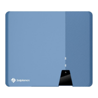
Step 1:Stri mm o the cable insulation.
Procedure:
Cable requirements:
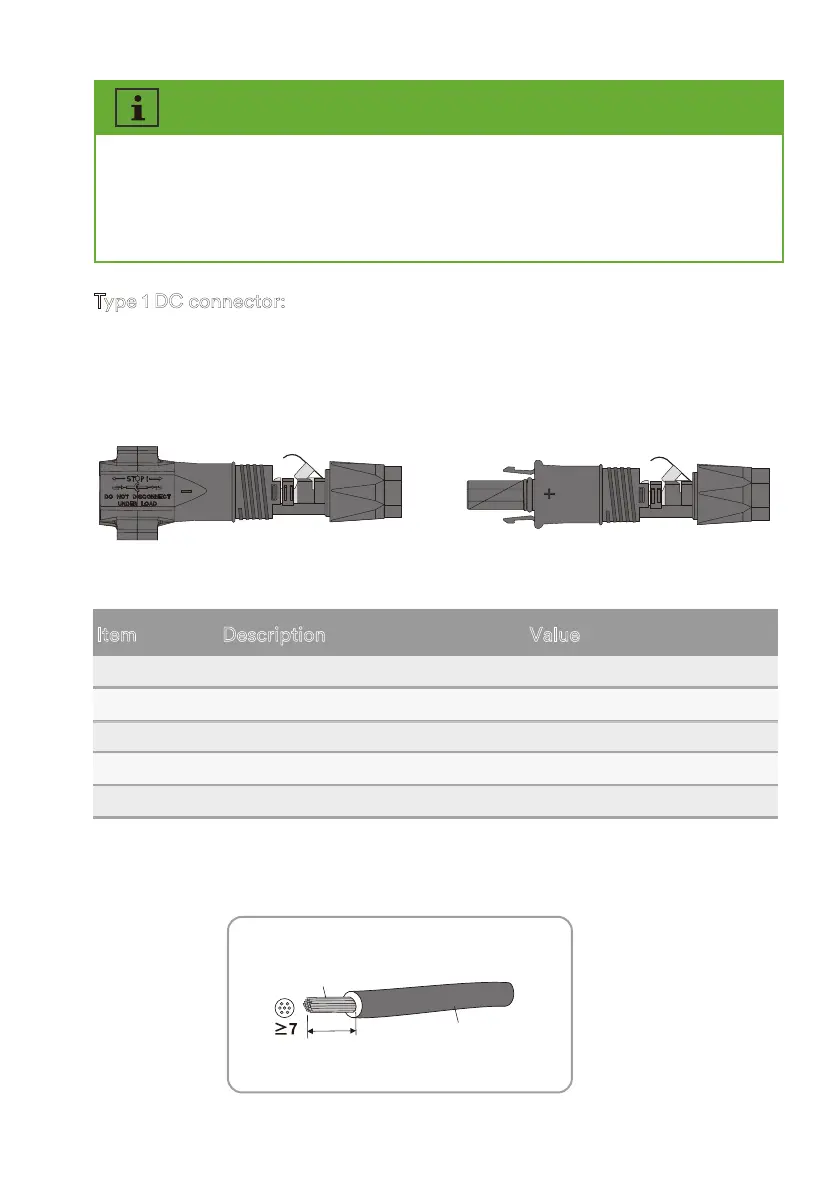
Type 1 DC connector:
2.5-6mm
2
Φ -5 8mm
12mm
Assemble the DC connectors as described below. Be sure to observe the correct polarity. The DC
connectors are marked with the symbols “+” and “-”.
A B
4
5
3
2
External diameter
Conductor cross-section
Number of copper wires
Description
5-8mm
Item
Value
1
Cable type
At least 7
PV cable
2.5-6mm²
The rated voltage
v
or connection to the inverter, all P module connection cable must be tted with the DC
connectors rovided. There may be two dierent tye DC connector shied randomly.
Assemble the DC connectors as described in the following.
UM0035_ASW05-12kH-T2-T3_EN_V01_0523